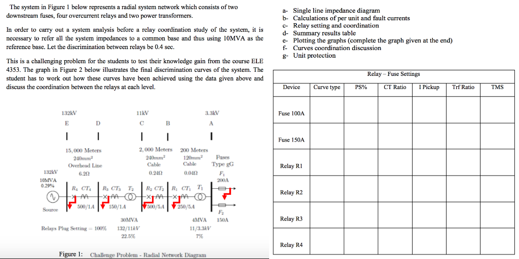
The system in Figure 1 below represents a radial system network which consists of two downstream fuses, four overcurrent relays and two power transformers. In order to carry out a system analysis before a relay coordination study of the system, it is necessary to refer all the system impedances to a common base and thus using 10MVA as the reference base. Let the discrimination between relays be 0.4 sec. a- Single line impedance diagram b- Calculations of per unit and fault currents C- Relay setting and coordination d- Summary results table e- Plotting the graphs (complete the graph given at the end) f- Curves coordination discussion g- Unit protection This is a challenging problem for the students to test their knowledge gain from the course ELE 4353. The graph in Figure 2 below illustrates the final discrimination curves of the system. The student has to work out how these curves have been achieved using the data given above and discuss the coordination between the relays at each level. Relay - Fuse Settings Device Curve type PS% CT Ratio I Pickup Trf Ratio TMS 3.3kV Fuse 100A 132kV ED 11kV CB Fuse 150A 15,000 Meters 240mm Overhead Line 2.000 Meters 240mm Cable 0.240 200 Meters 120mm2 Cable 0.040 Fuses Type gG F Relay R1 132kV 10MVA 0.29% 200A Relay R2 R. CTRCT, TRCT, RC, TB FAXTAO +TAA x40 T 500/ 1 150/14 500/5A260/5AEB 1 F 150A Relay R3 Relays Plug Setting = 100% 30MVA 132/11kV 22.5% 4MVA 11/3.3kV 7% Relay R4 Figure 1: Challenge Problem - Radial Network Diagram The system in Figure 1 below represents a radial system network which consists of two downstream fuses, four overcurrent relays and two power transformers. In order to carry out a system analysis before a relay coordination study of the system, it is necessary to refer all the system impedances to a common base and thus using 10MVA as the reference base. Let the discrimination between relays be 0.4 sec. a- Single line impedance diagram b- Calculations of per unit and fault currents C- Relay setting and coordination d- Summary results table e- Plotting the graphs (complete the graph given at the end) f- Curves coordination discussion g- Unit protection This is a challenging problem for the students to test their knowledge gain from the course ELE 4353. The graph in Figure 2 below illustrates the final discrimination curves of the system. The student has to work out how these curves have been achieved using the data given above and discuss the coordination between the relays at each level. Relay - Fuse Settings Device Curve type PS% CT Ratio I Pickup Trf Ratio TMS 3.3kV Fuse 100A 132kV ED 11kV CB Fuse 150A 15,000 Meters 240mm Overhead Line 2.000 Meters 240mm Cable 0.240 200 Meters 120mm2 Cable 0.040 Fuses Type gG F Relay R1 132kV 10MVA 0.29% 200A Relay R2 R. CTRCT, TRCT, RC, TB FAXTAO +TAA x40 T 500/ 1 150/14 500/5A260/5AEB 1 F 150A Relay R3 Relays Plug Setting = 100% 30MVA 132/11kV 22.5% 4MVA 11/3.3kV 7% Relay R4 Figure 1: Challenge Problem - Radial Network Diagram


