Question: undefined Q1. Figure (1) shows a second order system, G(s): i. Design a las compensator, Gs), such that closed loop system has the following characteristics:
 undefined
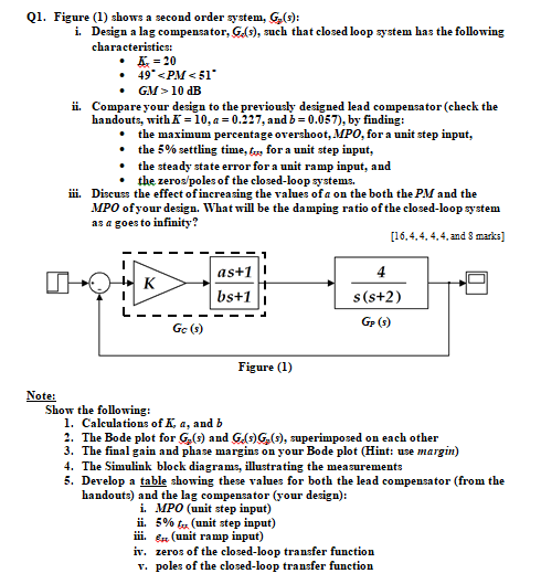
Q1. Figure (1) shows a second order system, G(s): i. Design a las compensator, Gs), such that closed loop system has the following characteristics: = 20 49 10 dB ii. Compare your design to the previously designed lead compensator (check the handouts, with K = 10, a = 0.227, and b = 0.057), by finding: the maximum percentage overshoot, MPO, for a unit step input, the 5% settling time, tv, for a unit step input, the steady state error for a unit ramp input, and the zeros/poles of the closed-loop systems. ji. Discuss the effect of increasing the values of a on the both the PM and the MPO of your design. What will be the damping ratio of the closed-loop system as a goes to infinity? [16.4.4.4.4 and 3 marks] as+1 K bs+1 4 s(s+2) Gp () Gc (3) Figure (1) Note: Show the following: 1. Calculations of K, a, and b 2. The Bode plot for G-(s) and GC) G(s), superimposed on each other 3. The final gain and phase margins on your Bode plot (Hint: use margin) 4. The Simulink block diagrams, illustrating the measurements 5. Develop a table showing these values for both the lead compensator (from the handouts) and the lag compensator (your design): i. MPO (unit step input) i. 5% tu (unit step input) j. & (unit ramp input) iv. zeros of the closed-loop transfer function v. poles of the closed-loop transfer function Q1. Figure (1) shows a second order system, G(s): i. Design a las compensator, Gs), such that closed loop system has the following characteristics: = 20 49 10 dB ii. Compare your design to the previously designed lead compensator (check the handouts, with K = 10, a = 0.227, and b = 0.057), by finding: the maximum percentage overshoot, MPO, for a unit step input, the 5% settling time, tv, for a unit step input, the steady state error for a unit ramp input, and the zeros/poles of the closed-loop systems. ji. Discuss the effect of increasing the values of a on the both the PM and the MPO of your design. What will be the damping ratio of the closed-loop system as a goes to infinity? [16.4.4.4.4 and 3 marks] as+1 K bs+1 4 s(s+2) Gp () Gc (3) Figure (1) Note: Show the following: 1. Calculations of K, a, and b 2. The Bode plot for G-(s) and GC) G(s), superimposed on each other 3. The final gain and phase margins on your Bode plot (Hint: use margin) 4. The Simulink block diagrams, illustrating the measurements 5. Develop a table showing these values for both the lead compensator (from the handouts) and the lag compensator (your design): i. MPO (unit step input) i. 5% tu (unit step input) j. & (unit ramp input) iv. zeros of the closed-loop transfer function v. poles of the closed-loop transfer function


