Answered step by step
Verified Expert Solution
Question
1 Approved Answer
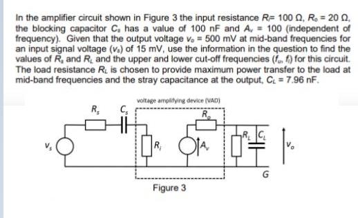
In the amplifier circuit shown in Figure 3 the input resistance R= 100 0, R. = 20 Q, the blocking capacitor C. has a

In the amplifier circuit shown in Figure 3 the input resistance R= 100 0, R. = 20 Q, the blocking capacitor C. has a value of 100 nF and A, = 100 (independent of frequency). Given that the output voltage v. = 500 mV at mid-band frequencies for an input signal voltage (v.) of 15 mV, use the information in the question to find the values of R, and R, and the upper and lower cut-off frequencies (f, f) for this circuit. The load resistance R. is chosen to provide maximum power transfer to the load at mid-band frequencies and the stray capacitance at the output, C = 7.96 nF. voltage amplilying device (VAD) R, R R, Figure 3
Step by Step Solution
★★★★★
3.44 Rating (151 Votes )
There are 3 Steps involved in it
Step: 1

Get Instant Access to Expert-Tailored Solutions
See step-by-step solutions with expert insights and AI powered tools for academic success
Step: 2

Step: 3

Document Format ( 2 attachments)
635df2b9a0529_180210.pdf
180 KBs PDF File
635df2b9a0529_180210.docx
120 KBs Word File
Ace Your Homework with AI
Get the answers you need in no time with our AI-driven, step-by-step assistance
Get Started


