

Question: For the circuit shown in Figure 4.1, the transistor parameters are (V_{T N}=0.6 mathrm{~V}, k_{n}^{prime}=80 mu mathrm{A} / mathrm{V}^{2}), and (lambda=0.015 mathrm{~V}^{-1}). Let (V_{D D}=5
For the circuit shown in Figure 4.1, the transistor parameters are \(V_{T N}=0.6 \mathrm{~V}, k_{n}^{\prime}=80 \mu \mathrm{A} / \mathrm{V}^{2}\), and \(\lambda=0.015 \mathrm{~V}^{-1}\). Let \(V_{D D}=5 \mathrm{~V}\).
(a) Design the transistor width-to-length ratio \(W / L\) and the resistance \(R_{D}\) such that \(I_{D Q}=0.5 \mathrm{~mA}, V_{G S Q}=1.2 \mathrm{~V}\), and \(V_{D S Q}=3 \mathrm{~V}\).
(b) Determine \(g_{m}\) and \(r_{o}\).
(c) Determine the small-signal voltage gain \(A_{v}=v_{o} / v_{i}\).
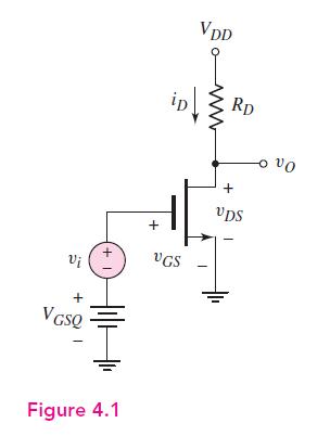
Vi + VGSQ +1 VDD RD + VGS + VDS Figure 4.1
Step by Step Solution
3.50 Rating (150 Votes )
There are 3 Steps involved in it

Get step-by-step solutions from verified subject matter experts