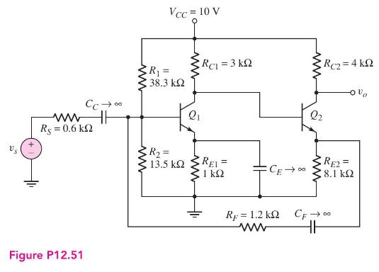
The circuit in Figure P12.51 is an example of a shunt-series feedback circuit. A signal proportional to
Question:
The circuit in Figure P12.51 is an example of a shunt-series feedback circuit. A signal proportional to the output current is fed back to the shunt connection at the base of \(Q_{1}\). However, the circuit may be used as a voltage amplifier. Assume transistor parameters of \(h_{F E}=120, V_{B E}(\mathrm{on})=0.7 \mathrm{~V}\), and \(V_{A}=\infty\).
(a) Determine the small-signal parameters for \(Q_{1}\) and \(Q_{2}\).
(b) Using nodal analysis, determine the small-signal voltage gain \(A_{v}=v_{o} / v_{s}\).

Fantastic news! We've Found the answer you've been seeking!
Step by Step Answer:
Related Book For 

Microelectronics Circuit Analysis And Design
ISBN: 9780071289474
4th Edition
Authors: Donald A. Neamen
Question Posted:


