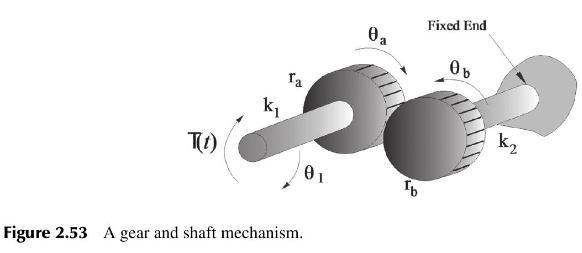
(a) Draw the free-body diagram of the gear and shaft mechanism shown below (Figure 2.53). (b) Find...
Question:
(a) Draw the free-body diagram of the gear and shaft mechanism shown below (Figure 2.53).
(b) Find expressions for the gear ratio, \(N\), and the angular displacements, \(\theta_{a}(t)\) and \(\theta_{b}(t)\).
(c) Find the equivalent stiffness constant \(k_{e q}\) such that the algebraic model of the system is given by
\[\theta_{1}=\frac{T(t)}{k_{e q}}\]
where \(k_{e q}\) is a function of \(k_{1}, k_{2}, r_{a}\), and \(r_{b}\).

Fantastic news! We've Found the answer you've been seeking!
Step by Step Answer:
Related Book For 

Design And Analysis Of Control Systems Driving The Fourth Industrial Revolution
ISBN: 9781032718804
2nd Edition
Authors: Arthur G O Mutambara
Question Posted:


