

Analog Voltmeter Design Figure P289 (a) shows a voltmeter circuit consisting of a DArsonval meter, two series
Question:
Analog Voltmeter Design Figure P2–89
(a) shows a voltmeter circuit consisting of a D’Arsonval meter, two series resistors, and a two-position selector switch.Acurrent of IFS ¼ 400 mAproduces full-scale deflection of the D’Arsonval meter, whose internal resistance is RM-25 V.
(a) Select the series resistance R1 and R2 so a voltage vx
¼ 100 V produces full-scale deflection when the switch is in position A, and voltage vx ¼ 10 V produces full-scale deflection when the switch is in position B.
(b) What is the voltage across the 20-kV resistor in Figure P2–89(b)?What is the voltage when the voltmeter in part
(a) is set to positionAand connected across the 20-kVresistor?What is the percentage error introduced connecting the voltmeter?
(c) A different D’Arsonval meter is available with an internal resistance of 100Vand a full-scale deflection current of 100 mA. If the voltmeter in part
(a) is redesigned using this D’Arsonval meter, would the error found in part
(b) be smaller or larger? Explain.AppendixLO1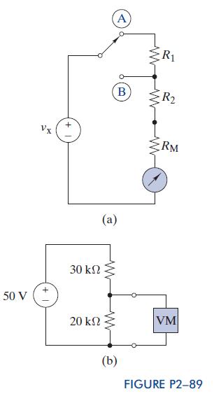
Step by Step Answer:


The Analysis And Design Of Linear Circuits
ISBN: 9781118214299
7th Edition
Authors: Roland E Thomas, Albert J Rosa, Gregory J Toussaint
