

Question: Programmable Voltage Divider Figure P288 shows a programmable voltage divider in which digital inputs b0 and b1 control complementary analog switches connecting a multitap voltage
Programmable Voltage Divider Figure P2–88 shows a programmable voltage divider in which digital inputs b0 and b1 control complementary analog switches connecting a multitap voltage divider to the analog output vO.
The switch positions in the figure apply when digital inputs are low.When inputs go high the switch positions reverse. Find the analog output voltage for (b1, b0) ¼ (0, 0), (0, 1), (1, 0), and
(1, 1) when VREF ¼ 12 V.AppendixLO1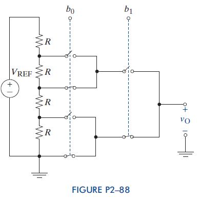
1 + VREFR R bo b1 R Vo R FIGURE P2-88
Step by Step Solution
There are 3 Steps involved in it
1 Expert Approved Answer
Step: 1 Unlock

Question Has Been Solved by an Expert!
Get step-by-step solutions from verified subject matter experts
Step: 2 Unlock
Step: 3 Unlock