

Question: The Fm signal is applied to the system shown in Figure consisting of a high-pass RC filter and an envelope detector. Assume that (a) The
The Fm signal is applied to the system shown in Figure consisting of a high-pass RC filter and an envelope detector. Assume that
(a) The resistance R is small compared with the reactance of the capacitor C for all significant frequency components of s (t), and
(b) The envelope detector does not load the filter. Determine the resulting signal at the envelope detector output, assuming that k?? | m (t) |
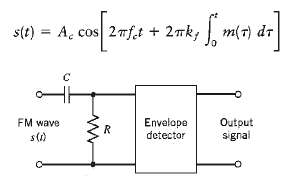
s(t) = A. cos 27ft + 2mk; m(7) dr FM wave Envelope detector Output R. signal s(1)
Step by Step Solution
3.34 Rating (166 Votes )
There are 3 Steps involved in it
The transfer function of the RC filter is Hf 32fCR Tj2mf CR ... View full answer

Get step-by-step solutions from verified subject matter experts
Document Format (1 attachment)
19-E-T-E-C-S (192).docx
120 KBs Word File