

Question: Include a two-input AND gate with the register of Fig. 2-6 and connect the gate output to the clock inputs of all the flip-flops. One
Include a two-input AND gate with the register of Fig. 2-6 and connect the gate output to the clock inputs of all the flip-flops. One input of the AND gate receives the clock pulses from the clock pulse generator. The other input of the AND gate provides a parallel load control. Explain the operation of the modified register.
Fig. 2-6
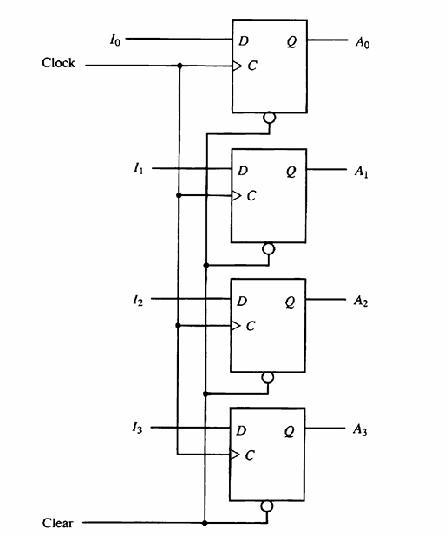
Clock Clear 10 "1 N 13 D D C D U D U e a e a Ao A A A3
Step by Step Solution
3.43 Rating (156 Votes )
There are 3 Steps involved in it
This means that the count value is updated immediately after the rising edge of the clock pulse The ... View full answer

Get step-by-step solutions from verified subject matter experts