

Question: In the Case Study of Section 1.4, an antenna azimuth angle is controlled, and its corresponding block diagram is shown in Figure 1.8(d) in the
In the Case Study of Section 1.4, an antenna azimuth angle is controlled, and its corresponding block diagram is shown in Figure 1.8(d) in the text. There, the sensor used to measure the antenna’s azimuth angle is a potentiometer.
a. Modify the block diagram if the sensor used to measure the antenna’s angle is an accelerometer.
b. Modify the block diagram if the sensor used to measure the antenna’s angle is a gyroscope.
Figure 1.8(d)
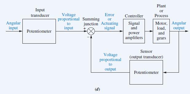
Plant Input or Voltage proportional Summing transducer Error Controller Process or Angular input junction Actuating signal Motor, Angular Signal and to input load, output Potentiometer power and amplifiers gears Sensor Voltage proportional (output transducer) to output Potentiometer (d)
Step by Step Solution
3.44 Rating (160 Votes )
There are 3 Steps involved in it

Get step-by-step solutions from verified subject matter experts