New Semester
Started
Get
50% OFF
Study Help!
--h --m --s
Claim Now
Question Answers
Textbooks
Find textbooks, questions and answers
Oops, something went wrong!
Change your search query and then try again
S
Books
FREE
Study Help
Expert Questions
Accounting
General Management
Mathematics
Finance
Organizational Behaviour
Law
Physics
Operating System
Management Leadership
Sociology
Programming
Marketing
Database
Computer Network
Economics
Textbooks Solutions
Accounting
Managerial Accounting
Management Leadership
Cost Accounting
Statistics
Business Law
Corporate Finance
Finance
Economics
Auditing
Tutors
Online Tutors
Find a Tutor
Hire a Tutor
Become a Tutor
AI Tutor
AI Study Planner
NEW
Sell Books
Search
Search
Sign In
Register
study help
engineering
engineering mechanics statics
Vector Mechanics For Engineers Statics And Dynamics 12th Edition Phillip J Cornwell, E Russell Jr Johnston, David Mazurek, E Russell Johnston Jr, Ferdinand P Beer, Brian - Solutions
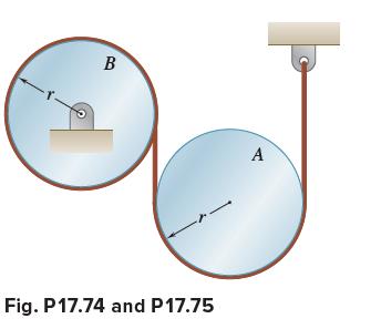
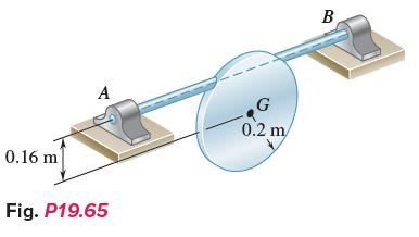
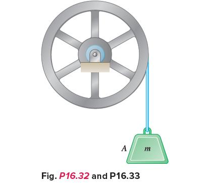
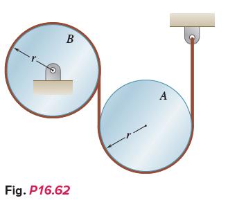
Two uniform cylinders, each of mass m = 6 kg and radius r = 125 mm, are connected by a belt as shown. If the system is released from rest when t = 0, determine (a) The velocity of the center of cylinder B at t = 3 s, (b) The tension in the portion of belt connecting the two cylinders. B Fig.
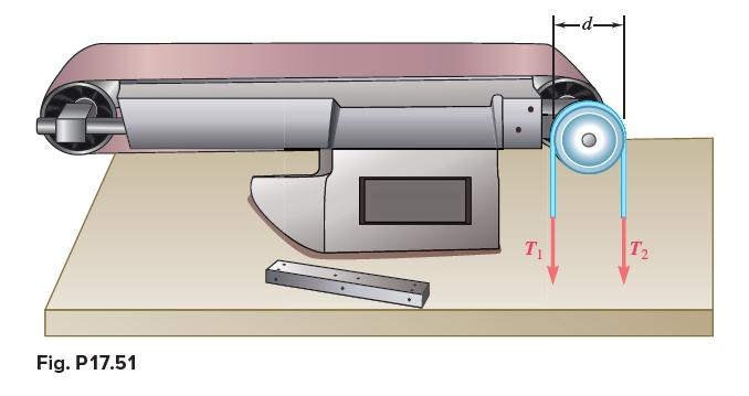
The drive belt on a vintage sander transmits ½ hp to a pulley that has a diameter of d = 4 in. Knowing that the pulley rotates at 1450 rpm, determine the tension difference T1 − T2 between the tight and slack sides of the belt. Fig. P17.51 T₁ T2
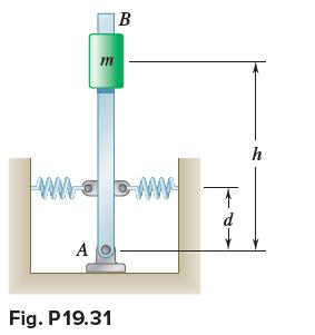
If h = 700 mm and d = 500 mm and each spring has a constant k = 600 N/m, determine the mass m for which the period of small oscillations is (a) 0.50 s, (b) Infinite. Neglect the mass of the rod and assume that each spring can act in both tension and compression. m A www. ww B Fig. P 19.31 ↑ d h
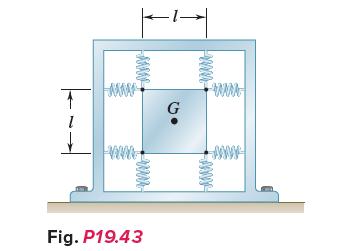
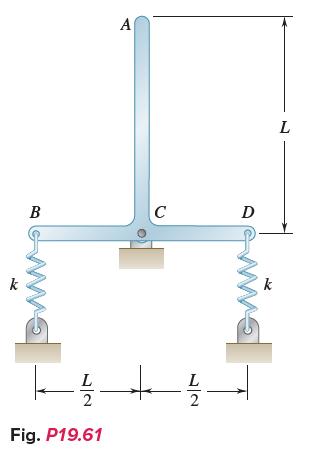
A square plate of mass m is held by eight springs, each of constant k. Knowing that each spring can act in either tension or compression, determine the frequency of the resulting vibration if (a) The plate is given a small vertical displacement and released, (b) The plate is rotated through a
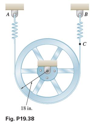
A belt is placed around the rim of a 500-lb flywheel and attached as shown to two springs, each of constant k = 85 lb/in. If end C of the belt is pulled 1.5 in. down and released, the period of vibration of the flywheel is observed to be 0.5 s. Knowing that the initial tension in the belt is
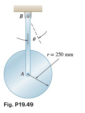
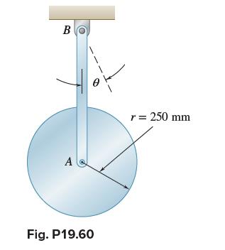
A uniform disk of radius r = 250 mm is attached at A to a 650-mm rod AB of negligible mass that can rotate freely in a vertical plane about B. Determine the period of small oscillations (a) If the disk is free to rotate in a bearing at A, (b) If the rod is riveted to the disk at A. B A 1 Fig.
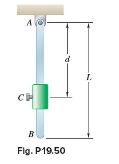
A small collar of mass 1 kg is rigidly attached to a 3-kg uniform rod of length L = 750 mm. Determine (a) The distance d to maximize the frequency of oscillation when the rod is given a small initial displacement, (b) The corresponding period of oscillation. A CH d B Fig. P 19.50 L
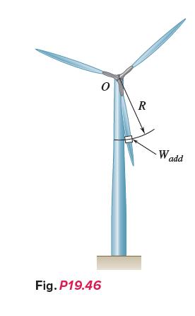
A three-blade wind turbine used for research is supported on a shaft so that it is free to rotate about O. One technique to determine the centroidal mass moment of inertia of an object is to place a known weight at a known distance from the axis of rotation and to measure the frequency of
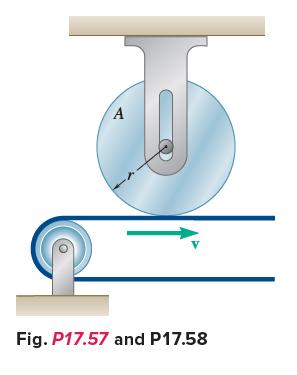
Disk A, of weight 5 lb and radius r = 3 in., is at rest when it is placed in contact with a belt that moves at a constant speed v = 50 ft/s. Knowing that μk = 0.20 between the disk and the belt, determine the time required for the disk to reach a constant angular velocity. A V Fig. P17.57 and
A uniform disk of radius r = 250 mm is attached at A to a 650-mm rod AB of negligible mass that can rotate freely in a vertical plane about B. If the rod is displaced 2° from the position shown and released, determine the magnitude of the maximum velocity of point A, assuming that the disk is (a)
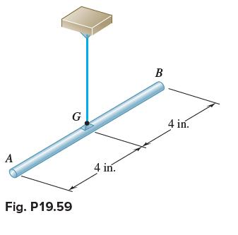
A 6-lb slender rod is suspended from a steel wire that is known to have a torsional spring constant K = 1.5 ft·lb/rad. If the rod is rotated through 180° about the vertical and released, determine (a) The period of oscillation, (b) The maximum velocity of end A of the rod. A G Fig. P19.59 4
Two uniform rods, each of weight W = 24 lb and length L = 40 in., are welded together to form the assembly shown. Knowing that the constant of each spring is k = 50 lb/ft and that end A is given a small displacement and released, determine the frequency of the resulting motion.
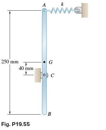
The 8-kg uniform bar AB is hinged at C and is attached at A to a spring of constant k = 500 N/m. If end A is given a small displacement and released, determine (a) The frequency of small oscillations, (b) The smallest value of the spring constant k for which oscillations will occur. 250 mm 40
The rotor of an electric motor has a mass of 25 kg, and it is observed that 4.2 min is required for the rotor to coast to rest from an angular velocity of 3600 rpm. Knowing that kinetic friction produces a couple of magnitude 1.2 N·m, determine the centroidal radius of gyration for the rotor.
A homogeneous rod of mass per unit length equal to 0.4 kg/m is used to form the assembly shown, which rotates freely about pivot A in a vertical plane. Knowing that the assembly is displaced 2° clockwise from its equilibrium position and released, determine its angular velocity and angular
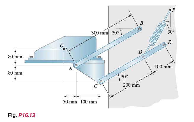
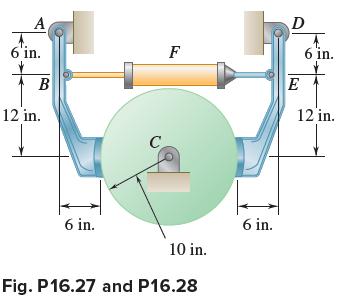
Three shafts and four gears are used to form a gear train that will transmit 7.5 kW from the motor at A to a machine tool at F. (Bearings for the shafts are omitted from the sketch.) Knowing that the frequency of the motor is 30 Hz, determine the magnitude of the couple that is applied to
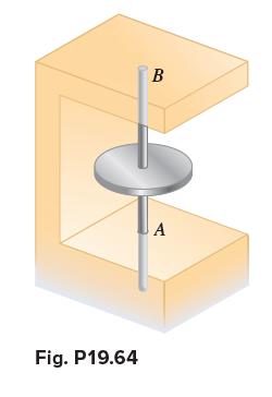
A uniform disk of radius r = 120 mm is welded at its center to two elastic rods of equal length with fixed ends at A and B. Knowing that the disk rotates through an 8° angle when a 500-mN·m couple is applied to the disk and that it oscillates with a period of 1.3 s when the couple is removed,
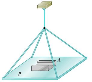
A horizontal platform P is held by several rigid bars that are connected to a vertical wire. The period of oscillation of the platform is found to be 2.2 s when the platform is empty and 3.8 s when an object A of unknown moment of inertia is placed on the platform with its mass center directly
A 60-kg uniform circular plate is welded to two elastic rods, which have fixed ends at supports A and B as shown. The torsional spring constant of each rod is 200 N·m/rad, and the system is in equilibrium when the plate is vertical. Knowing that the plate is rotated 2° about axis AB and released,
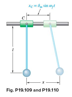
The 2.75-lb bob of a simple pendulum of length l = 24 in. is suspended from a 3-lb collar C. The collar is forced to move according to the relation xC = δm sin ωf t, with an amplitude δm = 0.4 in. and a frequency ff = 0.5 Hz. Determine (a) The amplitude of the motion of the bob, (b) The force
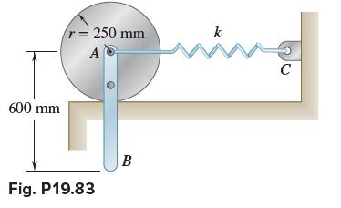
An 800-g rod AB is bolted to a 1.2-kg disk. A spring of constant k = 12 N/m is attached to the center of the disk at A and to the wall at C. Knowing that the disk rolls without sliding, determine the period of small oscillations of the system. 600 mm r = 250 mm A Fig. P19.83 B k M C
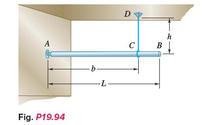
A uniform rod of length L is supported by a ball-and-socket joint at A and by a vertical wire CD. Derive an expression for the period of oscillation of the rod if end B is given a small horizontal displacement and then released. A Fig. P19.94 b -L- D C B h
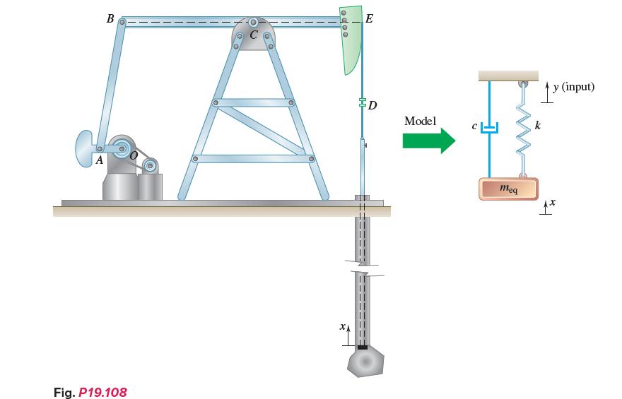
The crude-oil pumping rig shown is driven at 20 rpm. The inside diameter of the well pipe is 2 in., and the diameter of the pump rod is 0.75 in. The length of the pump rod and the length of the column of oil lifted during the stroke are essentially the same, and equal to 6000 ft. During the
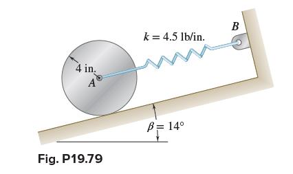
A 15-lb uniform cylinder can roll without sliding on an incline and is attached to a spring AB as shown. If the center of the cylinder is moved 0.4 in. down the incline and released, determine (a) The period of vibration, (b) The maximum velocity of the center of the cylinder. 4 in. A Fig.
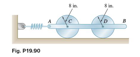
Two 12-lb uniform disks are attached to the 20-lb rod AB as shown. Knowing that the constant of the spring is 30 lb/in. and that the disks roll without sliding, determine the frequency of vibration of the system. www Fig. P19.90 A 8 in. 8 in. D B
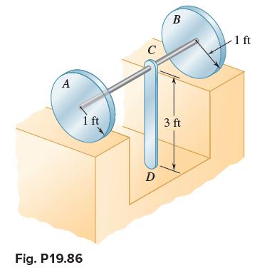
A 10-lb uniform rod CD is welded at C to a shaft of negligible mass that is welded to the centers of two 20-lb uniform disks A and B. Knowing that the disks roll without sliding, determine the period of small oscillations of the system. A Fig. P19.86 1 ft C D B 3 ft -1 ft
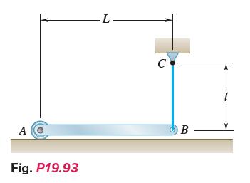
The motion of the uniform rod AB is guided by the cord BC and by the small roller at A. Determine the frequency of oscillation when the end B of the rod is given a small horizontal displacement and released. A Fig. P19.93 -L- с B 1
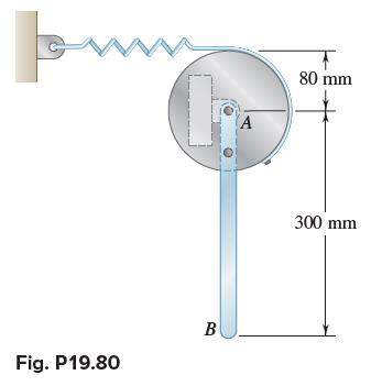
A 3-kg slender rod AB is bolted to a 5-kg uniform disk. A spring of constant 280 N/m is attached to the disk and is unstretched in the position shown. If end B of the rod is given a small displacement and released, determine the period of vibration of the system. ww Fig. P19.80 B A 80 mm 300 mm
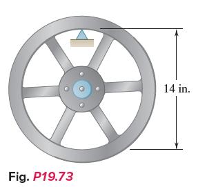
The inner rim of an 85-lb flywheel is placed on a knife edge, and the period of its small oscillations is found to be 1.26 s. Determine the centroidal moment of inertia of the flywheel. Fig. P19.73 14 in.
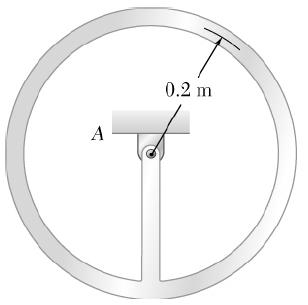
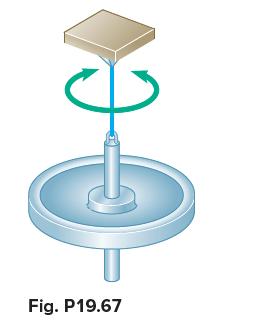
A period of 6.00 s is observed for the angular oscillations of a 4-oz gyroscope rotor suspended from a wire as shown. Knowing that a period of 3.80 s is obtained when a 1.25-in.-diameter steel sphere is suspended in the same fashion, determine the centroidal radius of gyration of the rotor.
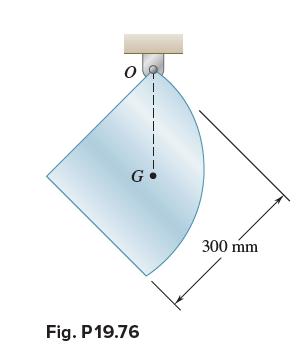
A thin uniform plate cut into the shape of a quarter circle can rotate in a vertical plane about a horizontal axis at point O. Determine the period of the small oscillations of the plate. I G! Fig. P 19.76 300 mm
Determine the period of small oscillations of a small particle that moves without friction inside a cylindrical surface of radius R. R Fig. P19.72
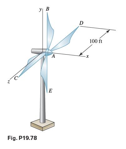
Blade AB of the experimental wind-turbine generator shown is to be temporarily removed. Motion of the turbine generator about the y axis is prevented, but the remaining three blades may oscillate as a unit about the x axis. Assuming that each blade can be modeled as a 100-ft slender rod, determine
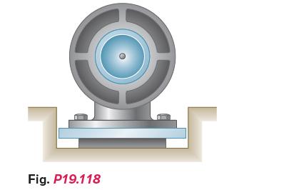
The unbalance of the rotor of a 400-lb motor is equivalent to a 3-oz weight located 6 in. from the axis of rotation. In order to limit to 0.2 lb the amplitude of the fluctuating force exerted on the foundation when the motor is run at speeds of 100 rpm and above, a pad is to be placed between the
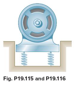
A motor weighing 400 lb is supported by springs having a total constant of 1200 lb/in. The unbalance of the rotor is equivalent to a 1-oz weight located 8 in. from the axis of rotation. Determine the range of allowable values of the motor speed if the amplitude of the vibration is not to exceed
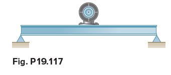
A 180-kg motor is bolted to a light horizontal beam. The unbalance of its rotor is equivalent to a 28-g mass located 150 mm from the axis of rotation, and the static deflection of the beam due to the weight of the motor is 12 mm. The amplitude of the vibration due to the unbalance can be decreased
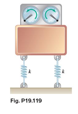
A motor of weight 100 lb is supported by four springs, each of constant 250 lb/in. The motor is constrained to move vertically, and the amplitude of its motion is observed to be 0.04 in. at a speed of 1200 rpm. Knowing that the weight of the rotor is 5 lb, determine the distance between the mass
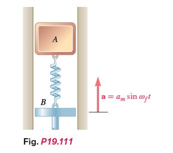
An 18-lb block A slides in a vertical frictionless slot and is connected to a moving support B by means of a spring AB of constant k = 8 lb/ft. Knowing that the acceleration of the support is a = am sin ωf t, where am = 5 ft/s2 and ωf = 6 rad/s, determine (a) The maximum displacement of block
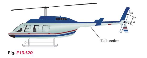
One of the tail rotor blades of a helicopter has an unbalanced weight of 1 lb at a distance of e = 6 in. from the axis of rotation. The fuselage can be considered to be fixed, and the tail rotor and tail can be modeled as an equivalent stiffness of 8800 lb/ft and an equivalent weight of 165 lb.
A counter-rotating eccentric mass exciter consisting of two rotating 100-g masses describing circles of radius r at the same speed but in opposite senses is placed on a machine element to induce a steadystate vibration of the element. The total mass of the system is 300 kg, the constant of each
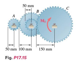
Gear A has a mass of 1 kg and a radius of gyration of 30 mm; gear B has a mass of 4 kg and a radius of gyration of 75 mm; gear C has a mass of 9 kg and a radius of gyration of 100 mm. The system is at rest when a couple M0 of constant magnitude 4 N·m is applied to gear C. Assuming that no slipping
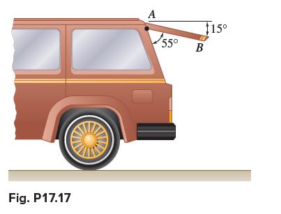
The 15-kg rear hatch of a vehicle opens as shown and can be modeled as a uniform 0.6-m long slender rod. Knowing that the tailgate is released from rest in the position shown, determine the angular velocity of the tailgate as it impacts the car body. Fig. P17.17 A 55° $15⁰ B
A force P with a magnitude of 3 N is applied to a tape wrapped around the body indicated. Knowing that the body rests on a frictionless horizontal surface, determine the acceleration of (a) Point A, (b) Point BA uniform disk of mass 2.4 kg. N Fig. P16.51 A C B P X
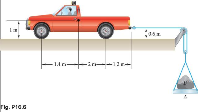
A 2000-kg truck is being used to lift a 400-kg boulder B that is on a 50-kg pallet A. Knowing the acceleration of the rear-wheel-drive truck is 1 m/s2, determine (a) The reaction at each of the front wheels, (b) The force between the boulder and the pallet. 1 m Fig. P16.6 1.4 m- -2 m- 1.2 m 0.6
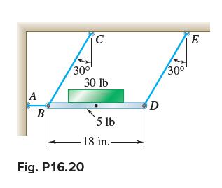
The coefficients of friction between the 30-lb block and the 5-lb platform BD are μs = 0.50 and μk = 0.40. Determine the accelerations of the block and of the platform immediately after wire AB has been cut. A B 30⁰⁰ C 30 lb Fig. P16.20 5 lb -18 in. D 30⁰ E
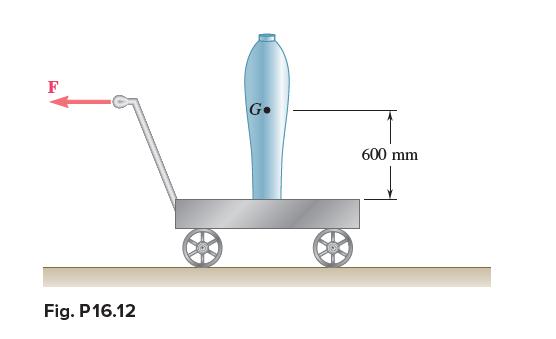
A 40-kg vase has a 200-mm-diameter base and is being moved using a 100-kg utility cart as shown. The cart moves freely (μ = 0) on the ground. Knowing the coefficient of static friction between the vase and the cart is μs = 0.4, determine the maximum force F that can be applied if the vase is not
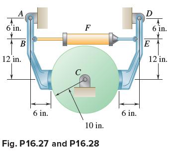
The 10-in.-radius brake drum is attached to a larger flywheel that is not shown. The total mass moment of inertia of the drum and the flywheel about point C is 15 lb·ft·s2, and the coefficient of kinetic friction between the drum and the brake shoes is 0.35. When the hydraulic cylinder F is
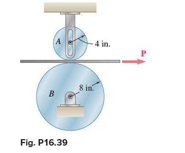
A belt of negligible mass passes between cylinders A and B and is pulled to the right with a force P. Cylinders A and B weigh, respectively, 5 and 20 lb. The shaft of cylinder A is free to slide in a vertical slot and the coefficients of friction between the belt and each of the cylinders are μs =
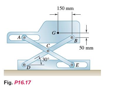
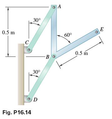
Members ACE and DCB are each 600 mm long and are connected by a pin at C. The mass center of the 10-kg member AB is located at G. Determine(a) The acceleration of AB immediately after the system has been released from rest in the position shown, (b) The corresponding force exerted by roller A on
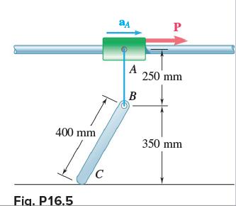
A uniform rod BC of mass 4 kg is connected to a collar A by a 250-mm cord AB. Neglecting the mass of the collar and cord, determine (a) The smallest constant acceleration aA for which the cord and the rod will lie in a straight line, (b) The corresponding tension in the cord. 400 mm Fig.
Disk A has a mass of 6 kg and an initial angular velocity of 360 rpm clockwise; disk B has a mass of 3 kg and is initially at rest. The disks are brought together by applying a horizontal force of magnitude 20 N to the axle of disk A. Knowing that μk = 0.15 between the disks and neglecting bearing
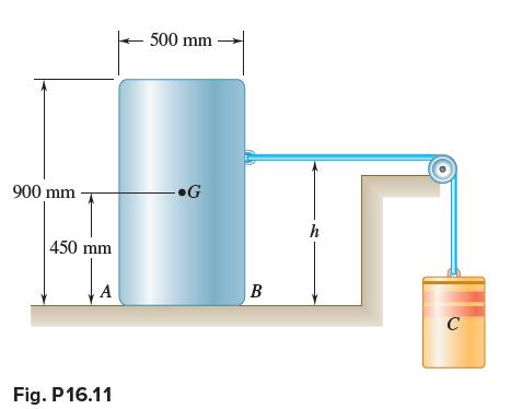
A completely filled barrel and its contents have a combined mass of 90 kg and a center of mass at G. A cylinder C with a mass of 200 kg is connected to the barrel as shown. Knowing μs = 0.40 and μk = 0.35, determine the maximum height h so the barrel will not tip. 900 mm 450 mm Fig. P16.11 500
A 60-lb uniform thin panel is placed in a truck with end A resting on a rough horizontal surface and end B supported by a smooth vertical surface. Knowing that the deceleration of the truck is 12 2ft/s, determine (a) The reactions at ends A and B, (b) The minimum required coefficient of static
The retractable shelf shown is supported by two identical linkage-andspring systems; only one of the systems is shown. A 20-kg machine is placed on the shelf so that half of its weight is supported by the system shown. If the springs are removed and the system is released from rest, determine (a)
A 60-lb uniform thin panel is placed in a truck with end A resting on a rough horizontal surface and end B supported by a smooth vertical surface. Knowing that the panel remains in the position shown, determine (a) The maximum allowable acceleration of the truck, (b) The corresponding minimum
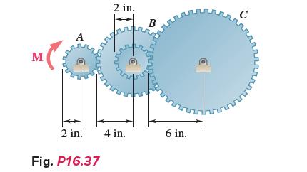
Gear A weighs 1 lb and has a radius of gyration of 1.3 in.; gear B weighs 6 lb and has a radius of gyration of 3 in.; gear C weighs 9 lb and has a radius of gyration of 4.3 in. Knowing a couple M of constant magnitude of 40 lb·in. is applied to gear A, determine (a) The angular acceleration of
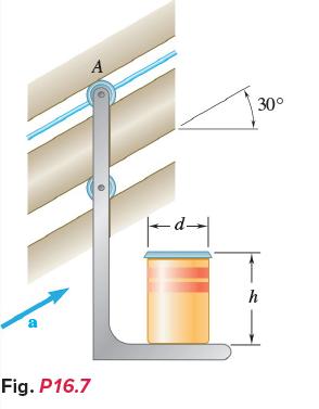
The support bracket shown is used to transport a cylindrical can from one elevation to another. Knowing that μs = 0.25 between the can and the bracket, determine (a) The magnitude of the upward acceleration a for which the can will slide on the bracket, (b) The smallest ratio h/d for which the
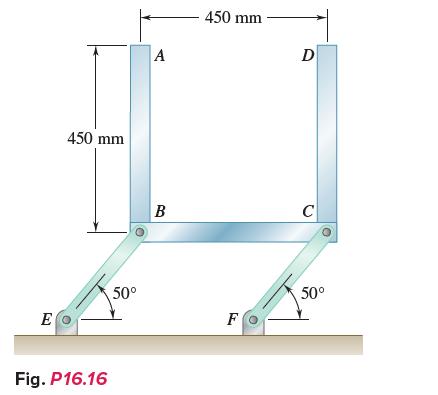
Three bars, each of mass 3 kg, are welded together and pin-connected to two links BE and CF. Neglecting the weight of the links, determine the force in each link immediately after the system is released from rest. E 450 mm Fig. P16.16 50° A B 450 mm- F D C 50°
Bars AB and BE, each with a mass of 4 kg, are welded together and are pin-connected to two links AC and BD. Knowing that the assembly is released from rest in the position shown and neglecting the masses of the links, determine (a) The acceleration of the assembly,(b) The forces in the links. 0.5
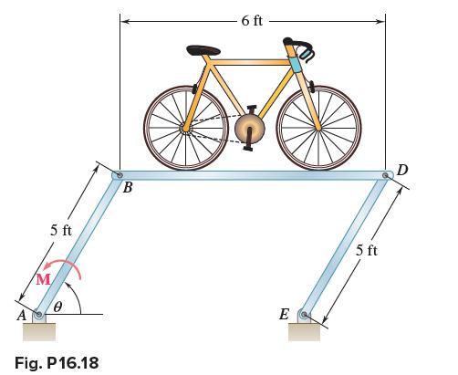
A prototype rotating bicycle rack is designed to save space at a train station. The combined weight of platform BD and the bicycle is 40 lb and is centered at 1 ft above the midpoint of the platform. The motor at A causes the support beam AB to have an angular velocity of 10 rpm and zero angular
The control rod AC is guided by two pins that slide freely in parallel curved slots of radius 200 mm. The rod has a mass of 10 kg, and its mass center is located at point G. Knowing that for the position shown the vertical component of the velocity of C is 1.25 m/s upward and the vertical component
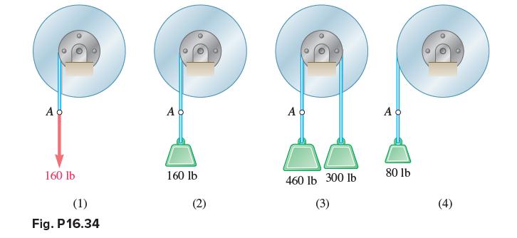
Each of the double pulleys shown has a mass moment of inertia of 15 lb·ft·s2 and is initially at rest. The outside radius is 18 in., and the inner radius is 9 in. Determine (a) The angular acceleration of each pulley, (b) The angular velocity of each pulley after point A on the cord has moved
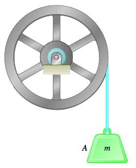
In order to determine the mass moment of inertia of a flywheel of radius 600 mm, a 12-kg block is attached to a wire that is wrapped around the flywheel. The block is released and is observed to fall 3 m in 4.6 s. To eliminate bearing friction from the computation, a second block of mass 24 kg is
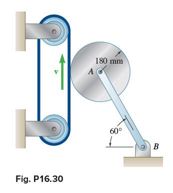
The 180-mm-radius disk is at rest when it is placed in contact with a belt moving at a constant speed. Neglecting the weight of the link AB and knowing that the coefficient of kinetic friction between the disk and the belt is 0.40, determine the angular acceleration of the disk while slipping
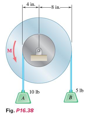
The 25-lb double pulley shown is at rest and in equilibrium when a constant 3.5-lb·ft couple M is applied. Neglecting the effect of friction and knowing that the radius of gyration of the double pulley is 6 in., determine (a) The angular acceleration of the double pulley, (b) The tension in each
Two uniform cylinders, each of weight W = 14 lb and radius r = 5 in., are connected by a belt as shown. If the system is released from rest, determine (a) The angular acceleration of each cylinder,(b) The tension in the portion of belt connecting the two cylinders, (c) The velocity of the center
The 10-in.-radius brake drum is attached to a larger flywheel that is not shown. The coefficient of kinetic friction between the drum and the brake shoe is 0.35 and the angular velocity of the flywheel is 360 rpm counterclockwise when the hydraulic cylinder shown exerts a force of 30 lb directed to
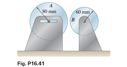
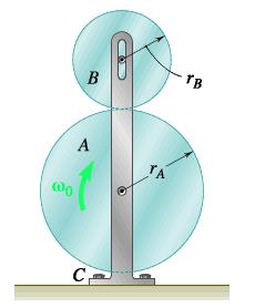
Disk A has a mass mA = 4 kg, a radius rA = 300 mm, and an initial angular velocity ω0 = 300 rpm clockwise. Disk B has a mass mB = 1.6 kg, a radius rB = 180 mm, and is at rest when it is brought into contact with disk A. Knowing that μk = 0.35 between the disks and neglecting bearing friction,
The flywheel shown has a radius of 20 in., a weight of 250 lb, and a radius of gyration of 15 in. A 30-lb block A is attached to a wire that is wrapped around the flywheel, and the system is released from rest. Neglecting the effect of friction, determine (a) The acceleration of block A, (b) The
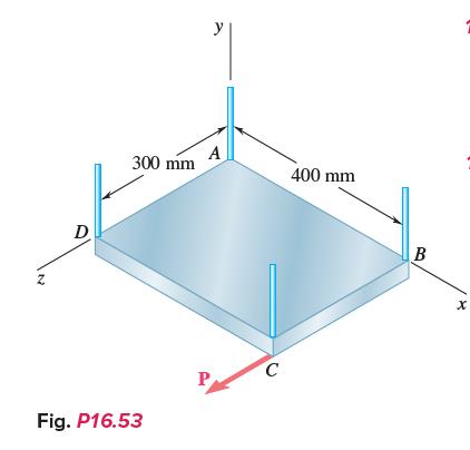
A rectangular plate of mass 5 kg is suspended from four vertical wires, and a force P of magnitude 6 N is applied to corner C as shown. Immediately after P is applied, determine the acceleration of (a) The midpoint of edge BC, (b) Corner B. N D 300 mm Fig. P16.53 y A C 400 mm B X
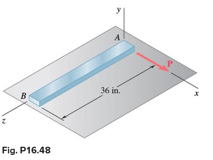
A uniform slender rod AB rests on a frictionless horizontal surface, and a force P of magnitude 0.75 lb is applied at A in a direction perpendicular to the rod. Knowing that the rod weighs 2 lb, determine (a) The acceleration of point A, (b) The acceleration of point B, (c) The location of the
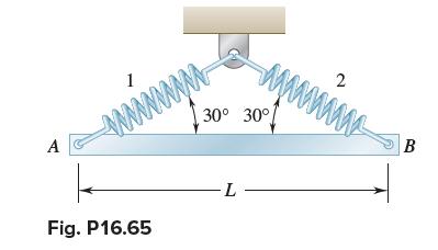
A uniform slender bar AB with a mass m is suspended from two springs as shown. If spring 2 breaks, determine at that instant (a) The angular acceleration of the bar, (b) The acceleration of point A, (c) The acceleration of point B. A 1 www Fig. P16.65 30° 30° -L- 2 www B
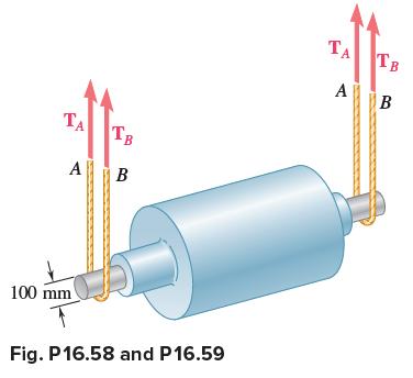
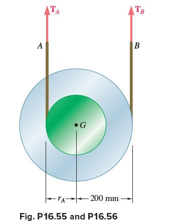
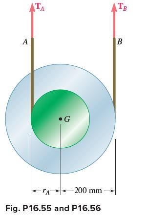
The steel roll shown has a mass of 1200 kg, a centroidal radius of gyration of 150 mm, and is lifted by two cables looped around its shaft. Knowing that for each cable TA = 3100 N and TB = 3300 N, determine (a) The angular acceleration of the roll, (b) The acceleration of its mass center.
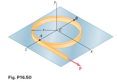
A force P with a magnitude of 3 N is applied to a tape wrapped around the body indicated. Knowing that the body rests on a frictionless horizontal surface, determine the acceleration of (a) Point A, (b) Point B.A thin hoop of mass 2.4 kg. N Fig. P16.50 A C B P X
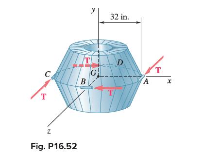
A 250-lb satellite has a radius of gyration of 24 in. with respect to the y axis and is symmetrical with respect to the zx plane. Its orientation is changed by firing four small rockets—A, B, C, and D—each of which produces a 4-lb thrust T directed as shown. Determine the angular acceleration
The steel roll shown has a mass of 1200 kg, has a centroidal radius of gyration of 150 mm, and is lifted by two cables looped around its shaft. Knowing that at the instant shown the acceleration of the roll is 150 mm/s2 downward and that for each cable TA = 3000 N, determine (a) The corresponding
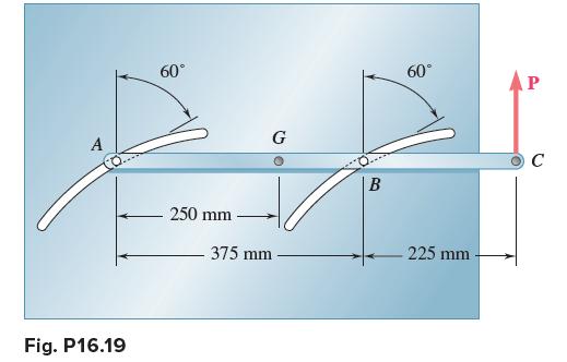
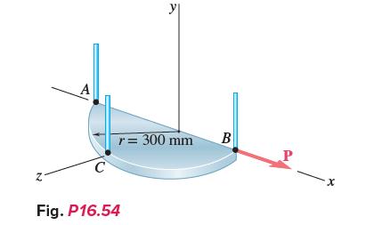
A uniform semicircular plate with a mass of 6 kg is suspended from three vertical wires at points A, B, and C, and a force P with a magnitude of 5 N is applied to point B. Immediately after P is applied, determine the acceleration of (a) The mass center of the plate, (b) Point C. y r = 300
A drum with a 200-mm radius is attached to a disk with a radius of rA = 150 mm. The disk and drum have a combined mass of 5 kg and a combined radius of gyration of 120 mm and are suspended by two cords. Knowing that TA = 35 N and TB = 25 N, determine the accelerations of points A and B on the
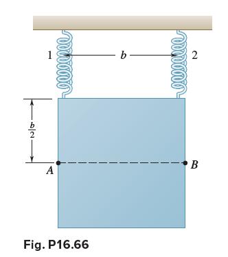
A thin plate of the shape indicated and of mass m is suspended from two springs as shown. If spring 2 breaks, determine the acceleration at that instant of (a) Point A, (b) Point B. 2 Vood Ø Ø Ø Ø b- vor o o o o o B I A Fig. P16.66
A drum with a 200-mm radius is attached to a disk with a radius of rA = 140 mm. The disk and drum have a combined mass of 5 kg and are suspended by two cords. Knowing that the acceleration of point B on the cord is zero, TA = 40 N, and TB = 20 N, determine the combined radius of gyration of the
The rotor of an electric motor has an angular velocity of 3600 rpm when the load and power are cut off. The 120-lb rotor, which has a centroidal radius of gyration of 9 in., then coasts to rest. Knowing that kinetic friction results in a couple of magnitude 2.5 lb·ft exerted on the rotor,
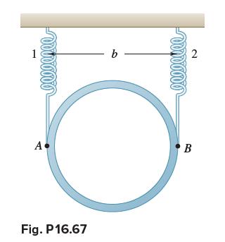
A thin plate of the shape indicated and of mass m is suspended from two springs as shown. If spring 2 breaks, determine the acceleration at that instant of (a) Point A, (b) Point B. 1 www A• Fig. P16.67 b no o o o o 2 B
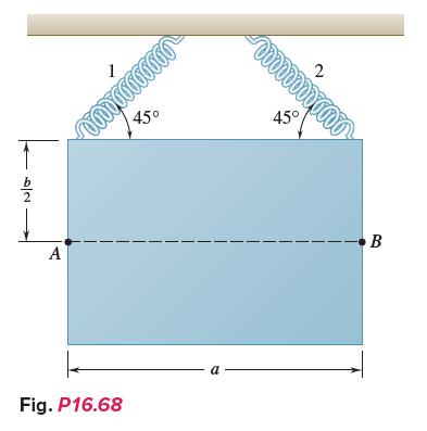
A thin plate of the shape indicated and of mass m is suspended from two springs as shown. If spring 2 breaks, determine the acceleration at that instant of (a) Point A, (b) Point B. 2 A 1 Fig. P16.68 00000000000 45° a weeeeeeee 45° 2 • B
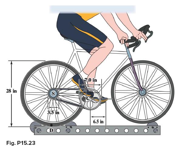
A cyclist uses a stationary trainer during the winter to keep in shape. Knowing that she pushes down on her pedal with a velocity of 26 in./s that increases at a rate of 2 in./s2, determine the velocity and acceleration of point D on the bottom of the rear wheel. 28 in Fig. P15.23 S 3.5 in 7.0
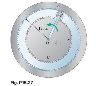
At the instant shown, the angular velocity of crank OB is 100 rpm in the counterclockwise direction. Knowing that gear C is fixed, determine (a) The angular velocity of the planetary gear B, (b) The angular velocity of the ring gear A. លលោ ណណណាលកណ ប 12 in. សហ A 0 Fig.
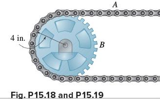
The sprocket wheel and chain shown are initially at rest. If the wheel has a uniform angular acceleration of 90 rad/s2 counterclockwise, determine (a) The acceleration of point A of the chain, (b) The magnitude of the acceleration of point B of the wheel after 3 s. 4 in. A Ο ΟΠΟ ΟΠΟ
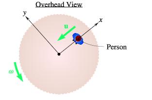
A person walks radially inward on a platform that is rotating counterclockwise about its center. Knowing that the platform has a constant angular velocity ω and the person walks with a constant speed u relative to the platform, what is the direction of the acceleration of the person at the instant
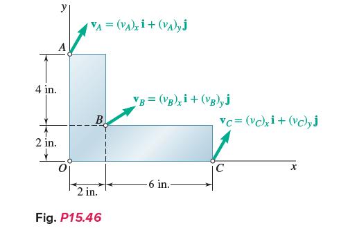
The plate shown moves in the xy plane. Knowing that (vA)x = 12 in./s, (vB)x = −4 in./s, and (vC)y = −24 in./s, determine(a) The angular velocity of the plate,(b) The velocity of point B, (c) The point of the plate with zero velocity. 4 in. 2 in. + VA = (VA)xi + (VA)yj B 2 in. Fig. P15.46 VB =
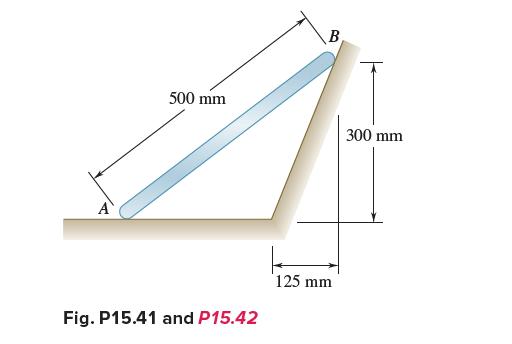
Rod AB can slide freely along the floor and the inclined plane. At the instant shown, the velocity of end A is 1.4 m/s to the left. Determine (a) The angular velocity of the rod, (b) The velocity of end B of the rod. 500 mm Fig. P15.41 and P15.42 125 mm B 300 mm
The sprocket wheel and chain shown are being operated at a speed of 600 rpm counterclockwise. When the power is turned off, it is observed that the wheel and chain coast to rest in 4s. Assuming uniformly decelerated motion, determine the magnitude of the velocity and acceleration of point B of the
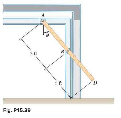
An overhead door is guided by wheels at A and B that roll in horizontal and vertical tracks. Knowing that when θ = 30° the velocity of wheel B is 2 ft/s downward, determine (a) The angular velocity of the door, (b) The velocity of end D of the door. 5 ft Fig. P15.39 A B 5 ft KINEN D
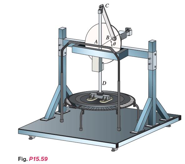
The test rig shown was developed to perform fatigue testing on fitness trampolines. A motor drives the 9-in.-radius flywheel AB, which is pinned at its center point A, in a counterclockwise direction. The flywheel is attached to slider CD by the 18-in. connecting rod BC. Knowing that the “feet”
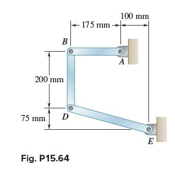
In the position shown, bar AB has an angular velocity of 10 rad/s counterclockwise. Determine the angular velocity of bars BD and DE. B 200 mm 75 mm D Fig. P15.64 - 175 mm → 100 mm A E
As steam is slowly injected into a turbine, the angular acceleration of the rotor is observed to increase linearly with the time t. Knowing that the rotor starts from rest at t = 0 and that after 10 s the rotor has completed 20 revolutions, write the equations of motion for the rotor and
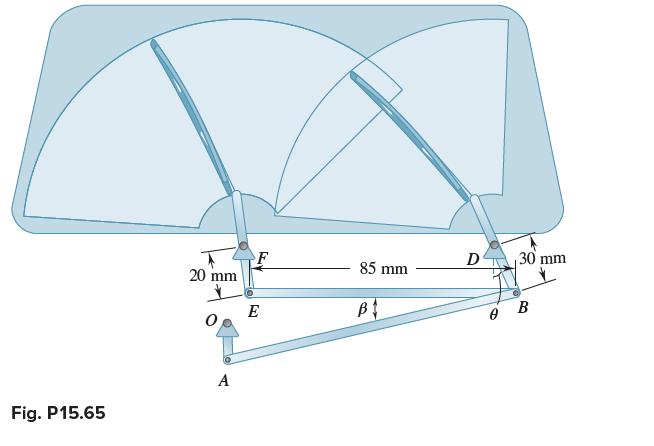
Linkage DBEF is part of a windshield wiper mechanism, where points O, F, and D are fixed pin connections. At the position shown, θ = 30° and link EB is horizontal. Knowing that link EF has a counterclockwise angular velocity of 4 rad/s at the instant shown, determine the angular velocity of links
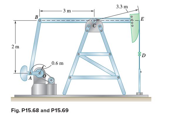
For the oil pump rig shown, link AB causes the beam BCE to oscillate as the crank OA revolves. Knowing that OA has a radius of 0.6 m and at the instant shown the velocity of point D is 1.5 m/s down, determine the angular velocity of arm AB and AO. 2 m A B -3 m 0.6 m Fig. P15.68 and P15.69 3.3
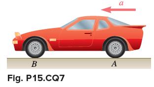
A rear wheel drive car starts from rest and accelerates to the left so that the tires do not slip on the road. What is the direction of the acceleration of the point on the tire in contact with the road, that is, Point A? a. ← b. ↖ c. ↑ d. ↓ e. ↙ B Fig. P15.CQ7 A a
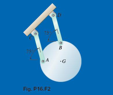
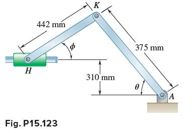
The right leg of an athlete on a rowing machine can be modeled as a linkage as shown, where A represents the ankle (which is stationary), K the knee, and H the hip. At the instant when θ = 75°, the shank AK has an angular velocity of 1 rad/s and an angular acceleration of 1.5 rad/s2, both
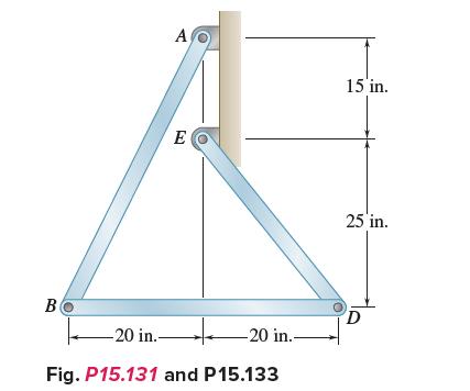
Knowing that at the instant shown bar AB has a constant angular velocity of 10 rad/s clockwise, determine the angular acceleration of (a) Bar BD, (b) Bar DE. B A E -20 in.. Fig. P15.131 and P15.133 -20 in.. 15 in. 25 in. D
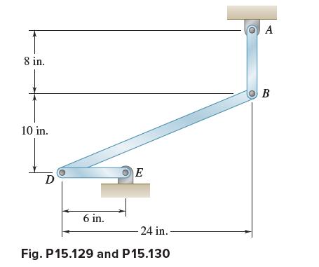
Knowing that the angular velocity of rod DE is a constant 20 rad/s clockwise, determine in the position shown (a) The angular acceleration of bar BD, (b) The angular acceleration of bar AB. 8 in. 10 in. D 6 in. E - 24 in.. Fig. P15.129 and P15.130 A B
Showing 100 - 200
of 2426
1
2
3
4
5
6
7
8
9
10
11
12
13
14
15
Last
Step by Step Answers