All Matches
Solution Library
Expert Answer
Textbooks
Search Textbook questions, tutors and Books
Oops, something went wrong!
Change your search query and then try again
Toggle navigation
FREE Trial
S
Books
FREE
Tutors
Study Help
Expert Questions
Accounting
General Management
Mathematics
Finance
Organizational Behaviour
Law
Physics
Operating System
Management Leadership
Sociology
Programming
Marketing
Database
Computer Network
Economics
Textbooks Solutions
Accounting
Managerial Accounting
Management Leadership
Cost Accounting
Statistics
Business Law
Corporate Finance
Finance
Economics
Auditing
Hire a Tutor
AI Study Help
New
Search
Search
Sign In
Register
study help
physics
principles communications systems
Questions and Answers of
Principles Communications Systems
Given a material for which χm = 3.1 and within which B = 0.4yaz T, find(a) H;(b) μ;(c) μr;(d) M;(e) J;(f) JB;(g) JT.
Find H in a material where(a) μr = 4.2, there are 2.7 × 1029 atoms/m3, and each atom has a dipole moment of 2.6 × 10⁻³⁰ay A·m2;(b) M = 270az A/m and μ = 2μ H/m;(c) χm = 0.7 and B = 2az T.(d)
Find the magnitude of the magnetization in a material for which(a) The magnetic flux density is 0.02 Wb/m2;(b) The magnetic field intensity is 1200 A/m and the relative permeability is 1.005;(c)
Under some conditions, it is possible to approximate the effects of ferromagnetic materials by assuming linearity in the relationship of B and H. Let μr = 1000 for a certain material of which a
Calculate values for Hϕ, Bϕ, and Mϕ at ρ = c for a coaxial cable with a = 2.5 mm and b = 6 mm if it carries a current I = 12 A in the center conductor, and μ = 3μH/m for 2.5mm < ρ < 3.5
Two current sheets, K0ay A/m at z = 0 and −K0ay A/m at z = d, are separated by an inhomogeneous material for which μr = az + 1, where a is a constant.(a) Find expressions for H and B in the
A conducting filament at z = 0 carries 12 A in the az direction. Let μr = 1 for ρ < 1 cm, μr = 6 for 1 < ρ < 2 cm, and μr = 1 for ρ > 2 cm. Find:(a) H everywhere;(b) B everywhere.
A long solenoid has a radius of 3 cm, 5000 turns/m, and carries current I = 0.25 A. The region 0 < ρ < a within the solenoid has μr = 5, whereas μr = 1 for a < ρ < 3 cm. Determine a
Let μr1 = 2 in region 1, defined by 2x + 3y − 4z > 1, while μr2 = 5 in region 2 where 2x + 3y − 4z < 1. In region 1, H1 = 50ax − 30ay + 20az A/m. Find(a) HN1;(b) Ht1;(c) Ht2;(d)
For values of B below the knee on the magnetization curve for silicon steel, approximate the curve by a straight line with μ = 5 mH/m. The core shown in Figure 8.16 has areas of 1.6
In Problem 8.28, the linear approximation suggested in the statement of the problem leads to flux density of 0.666 T in the central leg. Using this value of B and the magnetization curve for silicon
A rectangular core has fixed permeability μr >> 1, a square cross section of dimensions a × a, and has centerline dimensions around its perimeter of b and d. Coils 1 and 2, having turn
A toroid is constructed of a magnetic material having a cross-sectional area of 2.5 cm2 and an effective length of 8 cm. There is also a short air gap of 0.25 mm length and an effective area of 2.8
(a) Find an expression for the magnetic energy stored per unit length in a coaxial transmission line consisting of conducting sleeves of negligible thickness, having radii a and b. A medium of
Determine the energy stored per unit length in the internal magnetic field of an infinitely long, straight wire of radius a, carrying uniform current I .
The cones θ = 21¦ and θ = 159¦ are conducting surfaces and carry total currents of 40 A, as shown in Figure 8.17. The currents return on a
The dimensions of the outer conductor of a coaxial cable are b and c, where c > b. Assuming μ = μ0, find the magnetic energy stored per unit length in the region b < ρ < c for a uniformly
Find the inductance of the cone-sphere configuration described in Problem 8.35 and Figure 8.17. The inductance is that offered at the origin between the vertices of the cone.Figure 8.17 21° r= 0.25
A toroidal core has a rectangular cross section defined by the surfaces ρ = 2 cm, ρ = 3 cm, z = 4 cm, and z = 4.5 cm. The core material has a relative permeability of 80. If the core is wound with
A rectangular coil is composed of 150 turns of a filamentary conductor. Find the mutual inductance in free space between this coil and an infinite straight filament on the z axis if the four corners
Find the mutual inductance between two filaments forming circular rings of radii a and a, where a << a. The field should be determined by approximate methods. The rings are coplanar and
(a) Use energy relationships to show that the internal inductance of a nonmagnetic cylindrical wire of radius a carrying a uniformly distributed current I is μ0/(8π) H/m.(b) Find the internal
Show that the external inductance per unit length of a two-wire transmission line carrying equal and opposite currents is approximately (μ/π) ln(d/a) H/m, where a is the radius of each wire and d
In Figure 9.4, let B = 0.2 cos 120Ït T, and assume that the conductor joining the two ends of the resistor is perfect. It may be assumed that the magnetic field produced by I (t) is
In the example described by Figure 9.1, replace the constant magnetic flux density by the time-varying quantity B = B0sin Ït az. Assume that U is constant and that the displacement y of
Given H = 300az cos(3 × 10⁸t − y) A/m in free space, find the emf developed in the general aϕ direction about the closed path having corners at(a) (0, 0, 0), (1, 0, 0), (1, 1, 0), and (0, 1,
A rectangular loop of wire containing a high-resistance voltmeter has corners initially at (a/2, b/2, 0), (−a/2, b/2, 0), (−a/2,−b/2, 0), and (a/2,−b/2, 0). The loop begins to rotate about
The location of the sliding bar in Figure 9.5 is given by x = 5t + 2t3, and the separation of the two rails is 20 cm. Let B = 0.8x2azT. Find the voltmeter reading at(a) t = 0.4 s;(b) x = 0.6 m. এ
Let the wire loop of Problem 9.4 be stationary in its t = 0 position and find the induced emf that results from a magnetic flux density given by B(y, t) = B0 cos(ωt − βy) az, where ω and β are
A perfectly conducting filament is formed into a circular ring of radius a. At one point, a resistance R is inserted into the circuit, and at another a battery of voltage V0 is inserted. Assume that
A square filamentary loop of wire is 25 cm on a side and has a resistance of 125 per meter length. The loop lies in the z = 0 plane with its corners at (0, 0, 0), (0.25, 0, 0), (0.25, 0.25, 0), and
(a) Show that the ratio of the amplitudes of the conduction current density and the displacement current density is σ/ωε for the applied field E = Em cos ωt. Assume μ = μ0.(b) What is the
Let the internal dimensions of a coaxial capacitor be a = 1.2 cm, b = 4 cm, and l = 40 cm. The homogeneous material inside the capacitor has the parameters ε = 10−11 F/m, μ = 10−5 H/m, and σ =
Find the displacement current density associated with the magnetic field H = A1 sin(4x) cos(ωt − βz) ax + A2 cos(4x) sin(ωt − βz) az.
Consider the region defined by |x|, |y|, and |z| < 1. Let εr = 5, μr = 4, and σ = 0. If Jd = 20 cos(1.5 × 10⁸t − bx)ay μA/m2(a) Find D and E;(b) Use the point form of Faraday’s law and an
A voltage source V0 sin ωt is connected between two concentric conducting spheres, r = a and r = b, b > a, where the region between them is a material for which ∈ = ∈r ∈0, μ = μ0, and σ
Let μ = 3 × 10⁻⁵ H/m, ∈ = 1.2 × 10⁻¹⁰ F/m, and σ = 0 everywhere. If H = 2 cos(1010t − βx)az A/m, use Maxwell’s equations to obtain expressions for B, D, E, and β.
Derive the continuity equation from Maxwell’s equations.
The electric field intensity in the region 0 < x < 5, 0 < y < π/12, 0 < z < 0.06 m in free space is given by E = C sin 12y sin az cos 2 × 10¹⁰tax V/m. Beginning with the∇ × E
The parallel-plate transmission line shown in Figure 9.7 has dimensions b = 4 cm and d = 8 mm, while the medium between the plates is characterized by μr= 1, r= 20, and
Given Maxwell’s equations in point form, assume that all fields vary as est and write the equations without explicitly involving time.
(a) Show that under static field conditions, Eq. (55) reduces to Amp`eres circuital law.(b) Verify that Eq. (51) becomes Faradays law when we take the curl.E =
In a sourceless medium in which J = 0 and ρν = 0, assume a rectangular coordinate system in which E and H are functions only of z and t. The medium has permittivity ∈ and permeability μ.(a) If E
In region 1, z < 0, ∈1 = 2 × 10⁻¹¹ F/m, μ1 = 2 × 10⁻⁶ H/m, and σ1 = 4×10⁻³ S/m; in region 2, z > 0, ∈2 = ∈1/2, μ2 = 2μ1, and σ2 = σ1/4. It is known that E1 = (30ax + 20ay +
A vector potential is given as A = A0 cos(ωt − kz) ay.(a) Assuming as many components as possible are zero, find H, E, and V.(b) Specify k in terms of A0, ω, and the constants of the lossless
In a region where μr = ∈r = 1 and σ = 0, the retarded potentials are given by V = x(z − ct) V and A = x (z/c − t)az Wb/m, where c = 1√μ0 ∈0.(a) Show that ∇ · A = − μ∈
Write Maxwell’s equations in point form in terms of E and H as they apply to a sourceless medium, where J and ρv are both zero. Replace ∈ by μ, μ by ∈, E by H, and H by − E, and show that
The parameters of a certain transmission line operating at ω = 6×10⁸ rad/s are L = 0.35μH/m, C = 40 pF/m, G = 75 μS/m, and R = 17Ω/m. Find γ, α, β, λ, and Z0.
A sinusoidal voltage wave of amplitude V0, frequency ω, and phase constant β propagates in the forward z direction toward the open load end in a lossless transmission line of characteristic
Two characteristics of a certain lossless transmission line are Z0 = 50Ω and γ = 0 + j0.2π m−1 at f = 60 MHz(a) Find L and C for the line.(b) A load ZL = 60 + j80 is located at z = 0. What is
A transmitter and receiver are connected using a cascaded pair of transmission lines. At the operating frequency, line 1 has a measured loss of 0.1 dB/m, and line 2 is rated at 0.2 dB/m. The link is
An absolute measure of power is the dBm scale, in which power is specified in decibels relative to one milliwatt. Specifically, P(dBm) = 10 log10[P(mW)/1 mW]. Suppose that a receiver is rated as
A transmission line having primary constants L,C, R, and G has length ℓ and is terminated by a load having complex impedance RL + j XL. At the input end of the line, a dc voltage source, V0, is
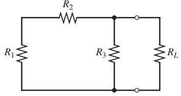
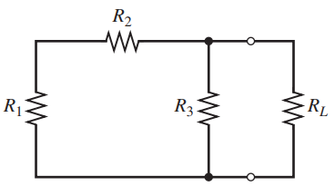
In a circuit in which a sinusoidal voltage source drives its internal impedance in series with a load impedance, it is known that maximum power transfer to the load occurs when the source and load
A lossless transmission line having characteristic impedance Z0 = 50 is driven by a source at the input end that consists of the series combination of a 10-V sinusoidal generator and a
For the transmission line represented in Figure 10.29, find Vs,outif f =(a) 60 Hz;(b) 500 kHz. 12 2 Lossless, v= 2c/3 120/0° V Z, = 50 2 80 2 out in 80 m
A 100- lossless transmission line is connected to a second line of 40- impedance, whose length is λ/4. The other end of the short line is terminated by a 25-Ω resistor. A sinusoidal wave (of
Determine the average power absorbed by each resistor in Figure 10.30. Lossless, v= 2c/3 Z, = 50 2 0.5/0° A 25 2 100 2 2.6 2
The line shown in Figure 10.31 is lossless. Find s on both sections 1 and 2. 0.2 2 50 Ω 100 2 Zo = 50 2 2 Z, = 50 Q -j 100 2
A lossless transmission line is 50 cm in length and operates at a frequency of 100 MHz. The line parameters are L = 0.2μH/m and C = 80 pF/m. The line is terminated in a short circuit at z = 0, and
(a) Determine s on the transmission line of Figure 10.32. The dielectric is air.(b) Find the input impedance.(c) If ÏL = 10Ω, find Is.(d) What value of L will produce a maximum
A lossless 75-Ω line is terminated by an unknown load impedance. A VSWR of 10 is measured, and the first voltage minimum occurs at 0.15 wavelengths in front of the load. Using the Smith chart,
The normalized load on a lossless transmission line is 2 + j 1. Let λ = 20 m and make use of the Smith chart to find(a) The shortest distance from the load to a point at which zin = rin + j0, where
With the aid of the Smith chart, plot a curve of |Zin| versus l for the transmission line shown in Figure 10.33. Cover the range 0 < l/λ < 0.25. 20 Ω Lossless Lossless 20 Ω Zo =
A 300- transmission line is short-circuited at z = 0. A voltage maximum, |V|max = 10 V, is found at z = −25 cm, and the minimum voltage, |V|min = 0, is at z = −50 cm. Use the Smith chart to find
A 50-Ω lossless line is of length 1.1 λ. It is terminated by an unknown load impedance. The input end of the 50-Ω line is attached to the load end of a lossless 75-Ω line. A VSWR of 4 is measured
The wavelength on a certain lossless line is 10 cm. If the normalized input impedance is zin = 1 + j 2, use the Smith chart to determine(a) s;(b) zL, if the length of the line is 12 cm;(c) xL, if zL
A standing wave ratio of 2.5 exists on a lossless 60 Ω line. Probe measurements locate a voltage minimum on the line whose location is marked by a small scratch on the line. When the load is
A two-wire line constructed of lossless wire of circular cross section is gradually flared into a coupling loop that looks like an egg beater. At the point X, indicated by the arrow in Figure 10.34,
In order to compare the relative sharpness of the maxima and minima of a standing wave, assume a load zL = 4 + j0 is located at z = 0. Let |V|min = 1 and λ = 1 m. Determine the width of the(a)
In Figure 10.17, let ZL= 40 ?? j10Ω, Z0= 50 Ω, f = 800 MHz, and v = c. (a) Find the shortest length d1 of a short-circuited stub, and the shortest distance d that it may be located from the
The lossless line shown in Figure 10.35 is operating with λ = 100 cm. If d1= 10 cm, d = 25 cm, and the line is matched to the left of the stub, what is ZL? d, s.c. Zg = 300 2 Z, = 300 2
A load, ZL = 25+ j75 Ω, is located at z = 0 on a lossless two-wire line for which Z0 = 50 and v = c.(a) If f = 300 MHz, find the shortest distance d (z = −d) at which the input admittance has a
The two-wire lines shown in Figure 10.36 are all lossless and have Z0= 200 . Find d and the shortest possible value for d1to provide a matched load if λ = 100 cm. S.C Matched 100 2
In the transmission line of Figure 10.20, Rg= Z0= 50 Ω, and RL= 25 Ω. Determine and plot the voltage at the load resistor and the current in the battery as functions of time
Repeat Problem 10.37, with Z0= 50 Ω, and RL= Rg= 25 Ω. Carry out the analysis for the time period 0 < t < 8l/ν.In ProblemIn the transmission line of Figure
In the transmission line of Figure 10.20, Z0= 50 Ω, and RL= Rg= 25 Ω. The switch is closed at t = 0 and is opened again at time t = l/4ν, thus creating a rectangular voltage pulse in the
In the charged line of Figure 10.25, the characteristic impedance is Z0= 100 , and Rg= 300 Ω. The line is charged to initial voltage, V0= 160 V, and the switch is closed at t = 0.
In the transmission line of Figure 10.37, the switch is located midway down the line and is closed at t = 0. Construct a voltage reflection diagram for this case, where RL= Z0. Plot the load resistor
A simple frozen wave generator is shown in Figure 10.38. Both switches are closed simultaneously at t = 0. Construct an appropriate voltage reflection diagram for the case in which RL= Z0. Determine
In Figure 10.39, RL= Z0and Rg= Z0/3. The switch is closed at t = 0. Determine and plot as functions of time(a) The voltage across RL;(b) The voltage across Rg;(c) The current through the battery. t
A parallel-plate capacitor is filled with a nonuniform dielectric characterized by ∈r = 2 + 2 × 106x2, where x is the distance from one plate in meters. If S = 0.02 m2 and d = 1 mm, find C.
An air-filled parallel-plate capacitor with plate separation d and plate area A is connected to a battery that applies a voltage V0 between plates. With the battery left connected, the plates are
Find the dielectric constant of a material in which the electric flux density is four times the polarization.
The surface x = 0 separates two perfect dielectrics. For x > 0, let r = r1 = 3, while r2 = 5 where x < 0. If E1 = 80ax − 60ay − 30az V/m, find(a) EN1;(b) ET1;(c) E1;(d) The angle θ1
Consider a coaxial capacitor having inner radius a, outer radius b, unit length, and filled with a material with dielectric constant, r. Compare this to a parallel-plate capacitor having plate width
Let S = 100 mm2, d = 3 mm, and ∈r = 12 for a parallel-plate capacitor.(a) Calculate the capacitance.(b) After connecting a 6-V battery across the capacitor, calculate E, D, Q, and the total stored
Consider the random process of Problem 7.4.(a) Find the time-average mean and the auto correlation function.(b) Find the ensemble-average mean and the auto correlation function.(c) Is this
A useful average in the consideration of noise in FM demodulation is the cross-correlation where y(t) is assumed stationary.(a) Show that
Consider the system shown in Figure 7.19 as a means of approximately measuring Rx(Ï) where x(t) is stationary.(a) Show that E[y] = Rx(Ï).(b) Find an expression for
A random process is composed of sample functions of the formwhere n(t) is a wide-sense stationary random process with the auto correlation function Rn(Ï), and nk = n(kTs).(a) If Ts is
Consider a signal-plus-noise process of the formz(t) = A cos 2π(f0 + fd)t + n (t)where ω0 = 2πf0, withn (t) = nc (t) cos ω0t - ns (t) sin ω0tan ideal band limited white-noise process with
A noise wave form n1(t) has the band limited power spectral density shown in Figure 7.18. Find and plot the power spectral density of n2 (t) = n1(t) cos(Ï0t + θ) - n1(t)
Find the noise-equivalent bandwidths for the following first- and second-order low pass filters in terms of their 3-dB bandwidths. Refer to Chapter 2 to determine the magnitudes of their transfer
Consider the random process of Example 7.1 with the pdf of θ given by (a) Find the statistical-average and time-average mean and variance.(b) Find the statistical-average and
(a) If Sn(f) = α2/ (α2+ 4Ï2f2) show that Rn(Ï) = Ke-α|Ï|. Find K.(b) Find Rn(Ï) if (c) If n (t) = nc (t)
The voltage of the output of a noise generator whose statistics are known to be closely Gaussian and stationary is measured with a dc voltmeter and a true root mean-square (rms) voltmeter that is ac
Which of the following functions are suitable auto correlation functions? Tell why or why not. (ω0, τ0, τ1, A, B, C, and f0 are positive constants.)(a) A cos ω0τ(b) AΛ (τ/ τ0), where Λ(x) is
A band limited white-noise process has a double sided power spectral density of 2 × 10⁻⁵ W/Hz in the frequency range |f| ≤ 1 kHz.Find the auto correlation function of the noise process.
Consider a random binary pulse waveform as an alyzed in Example 7.6, but with half-cosine pulses given by p(t) = cos(2πt / 2T)II(t / T). Obtain and sketch the auto correlation function for the two
Showing 600 - 700
of 1112
1
2
3
4
5
6
7
8
9
10
11
12