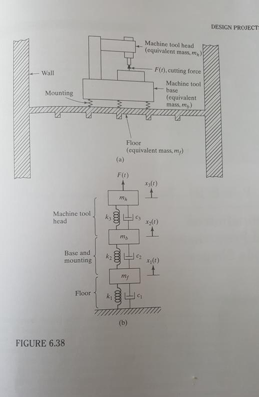
6.101 A heavy machine tool mounted on the first floor of a building, Fig. 6.38(a), has been modeled 5000 lb/in 50 lb-sec/in = as


6.101 A heavy machine tool mounted on the first floor of a building, Fig. 6.38(a), has been modeled 5000 lb/in 50 lb-sec/in = as a three degree of freedom system as indicated in Fig. 6.38(b). (a) For k 10 lb-sec/in., mf 1000 cos 60t lb, find the steady-state k = 500 lb/in., k3= 2000 lb/in., C = C = C3 10 lb-sec/in., mh mb 2 lb-sec/in., and F(t) = vibration of the system using the mechanical impedance method described in Section 5.6. (b) If the maximum response of the machine tool head (x3) has to be reduced by 25 percent, how should the stiffness of the mounting (k) be changed? (c) Is there any better way of achieving the goal stated in (b)? Provide details. Wall Mounting 5 Machine tool head Base and mounting FIGURE 6.38 Floor k k k (a) F(t) 0000 mh 0000 Floor (equivalent mass, mg) mb elle my Machine tool head (equivalent mass, m) (b) 9 F(t), cutting force Machine tool base (equivalent mass, m) x3(1) 1 x (1) t x (1) 1 DESIGN PROJECT:
Step by Step Solution
3.49 Rating (156 Votes )
There are 3 Steps involved in it
Step: 1
Ft Assume mechanical impedence 3311311 32111 311X K42 M n For steady state vibration 13 K ...
See step-by-step solutions with expert insights and AI powered tools for academic success
Step: 2

Step: 3

Ace Your Homework with AI
Get the answers you need in no time with our AI-driven, step-by-step assistance
Get Started


