

Question: EQUIPMENT PhET interactive simulation tool [Circuit Construction Kit: (AC+DC) - Virtual Lab] https://phet.colorado.edu/en/simulation/legacy/circuit-construction-kit-ac-virtual-lab See: 00-PhET Simulation Tool instructions for Electric Circuits Labs, on how to
![Lab] https://phet.colorado.edu/en/simulation/legacy/circuit-construction-kit-ac-virtual-lab See: 00-PhET Simulation Tool instructions for Electric Circuits Labs, on](https://s3.amazonaws.com/si.experts.images/answers/2024/06/66800a0cd2b95_21266800a0cb94f9.jpg)
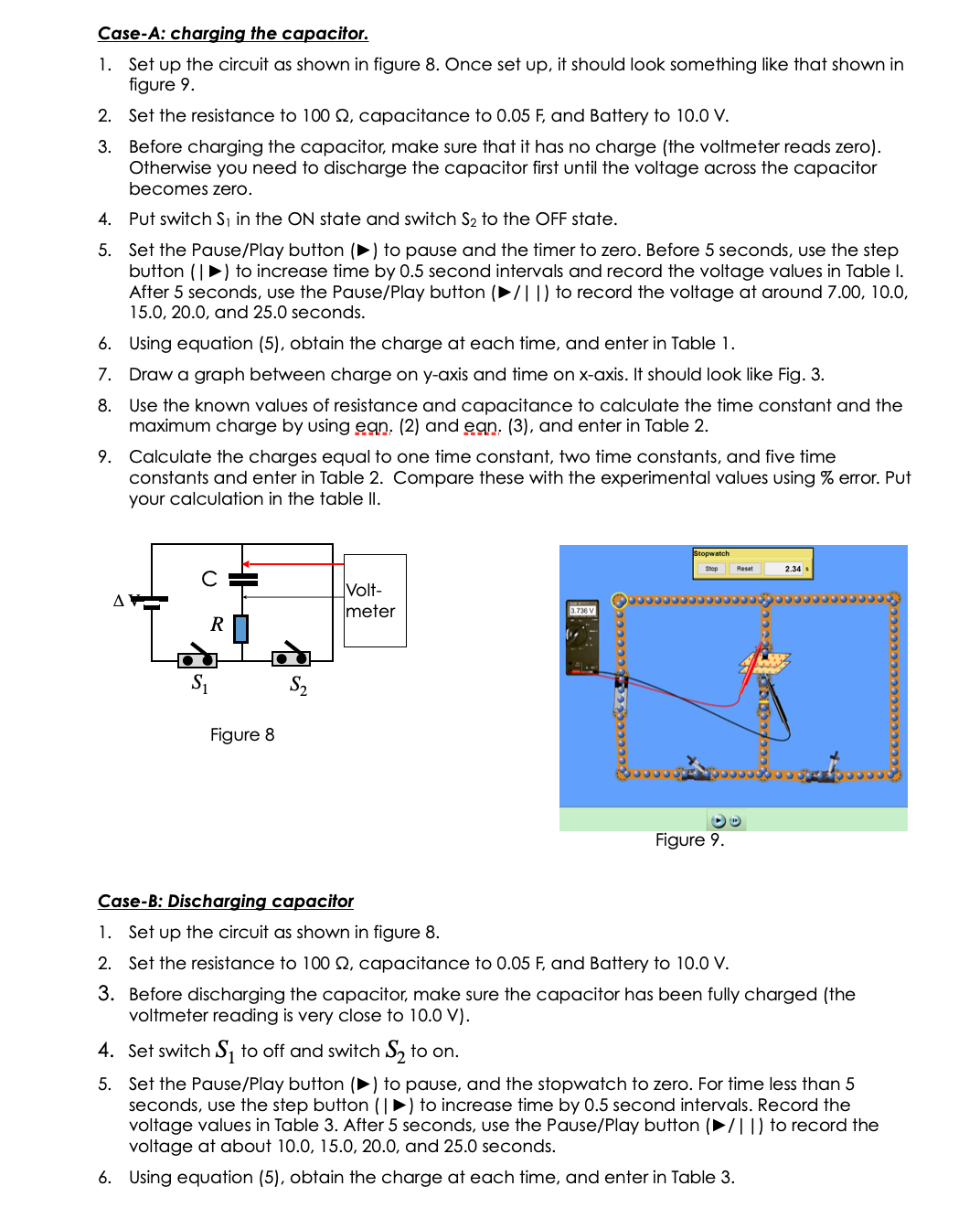
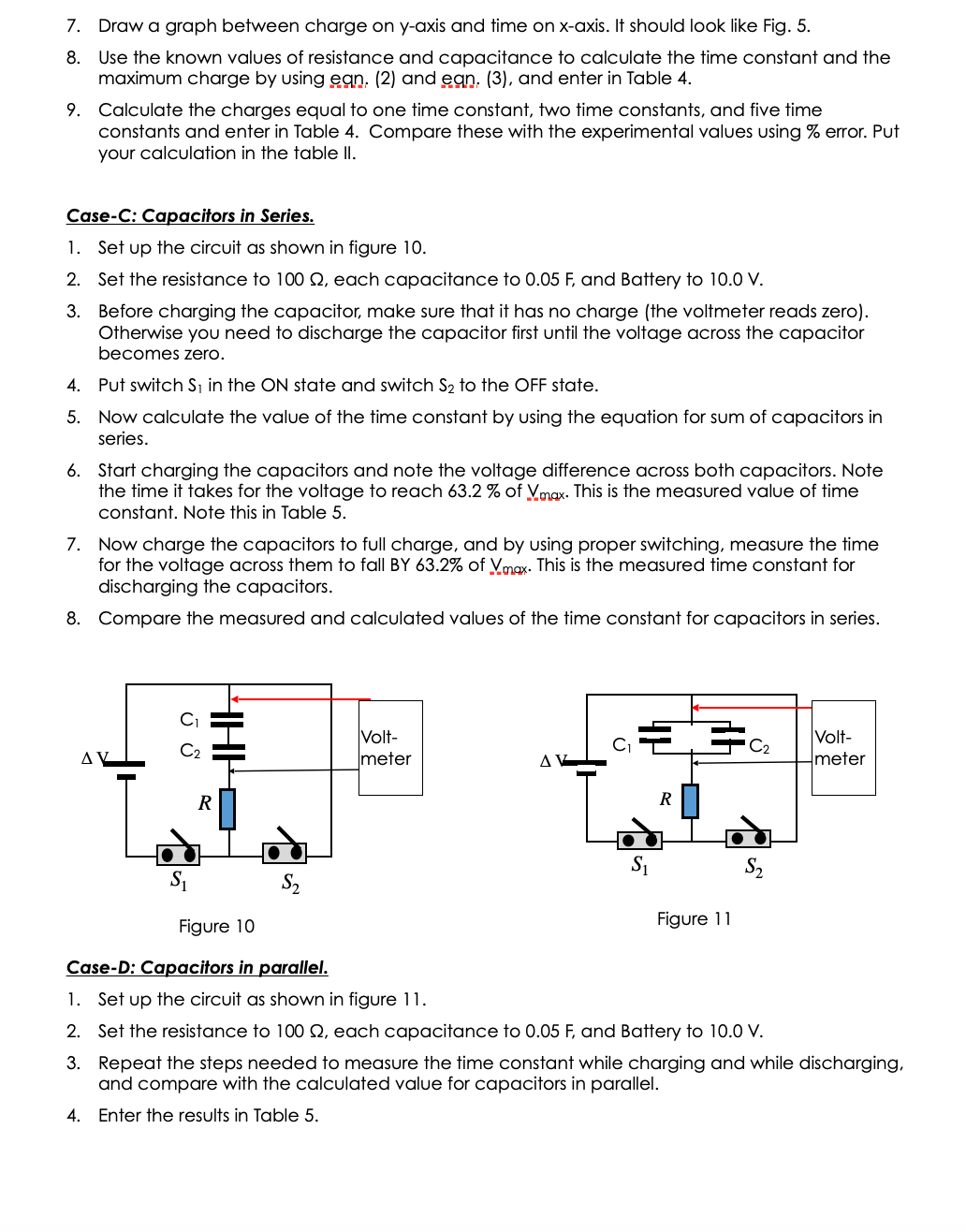
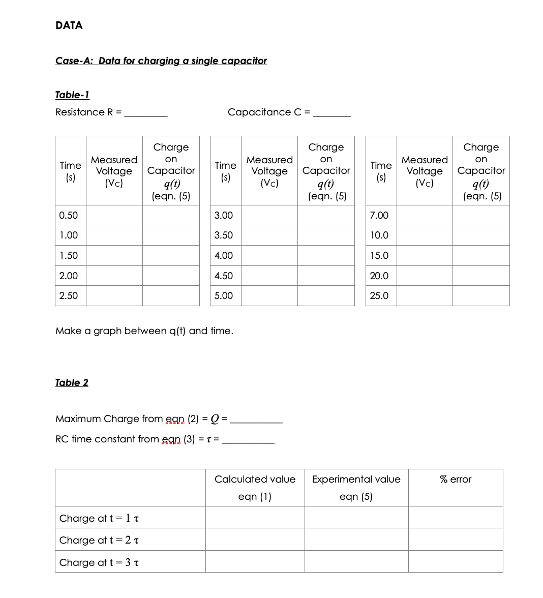
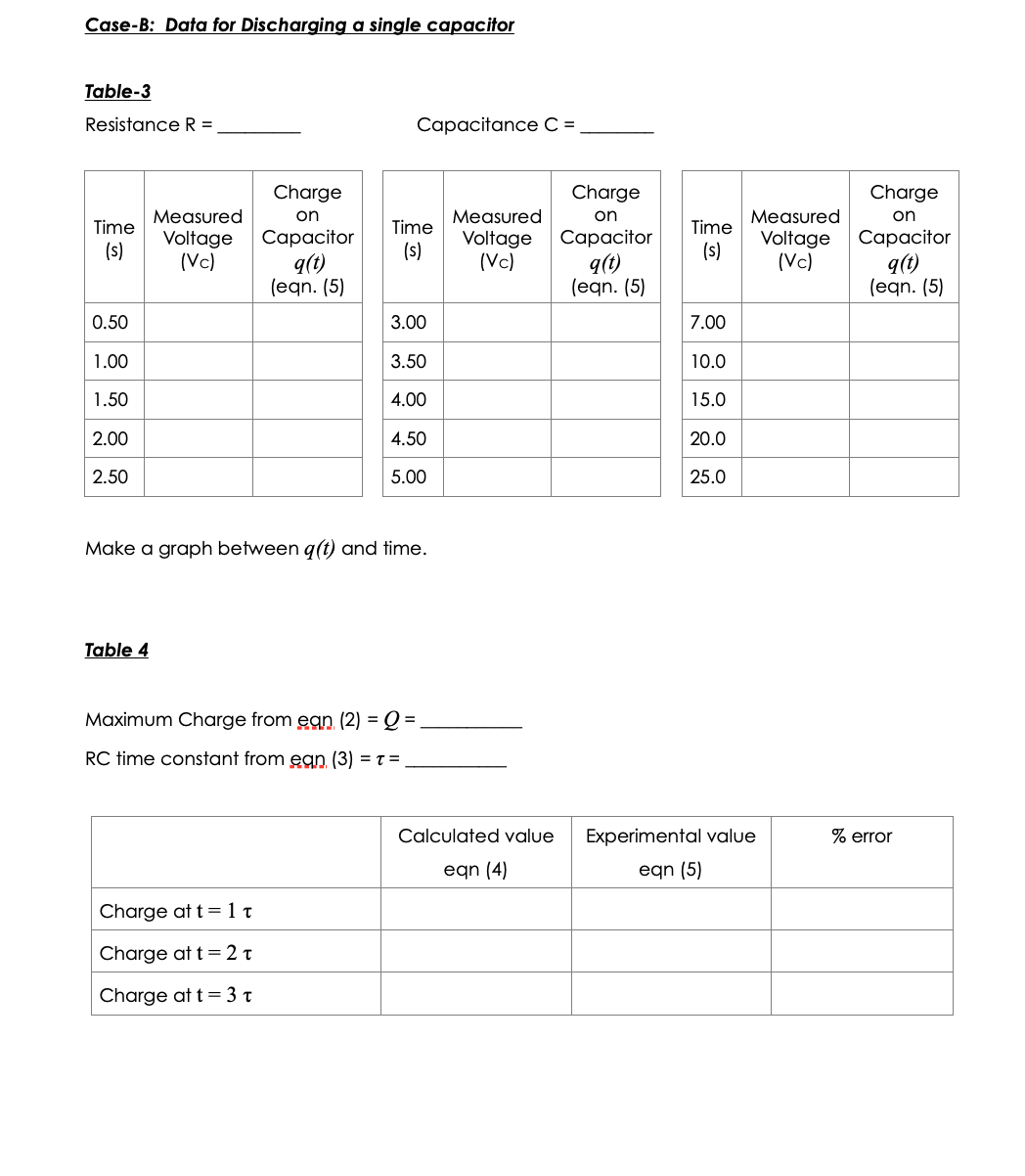
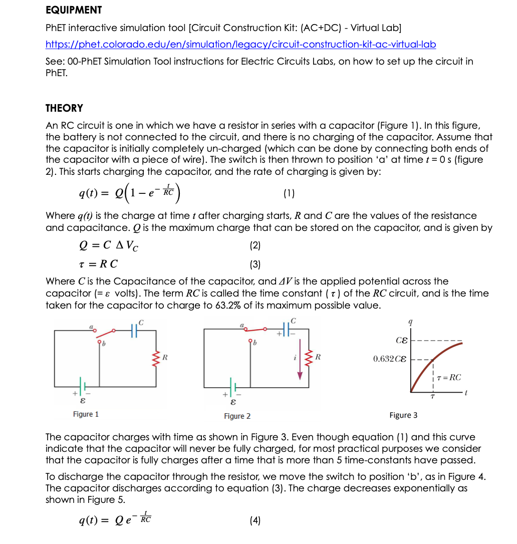
EQUIPMENT PhET interactive simulation tool [Circuit Construction Kit: (AC+DC) - Virtual Lab] https://phet.colorado.edu/en/simulation/legacy/circuit-construction-kit-ac-virtual-lab See: 00-PhET Simulation Tool instructions for Electric Circuits Labs, on how to set up the circuit in PhET . THEORY An RC circuit is one in which we have a resistor in series with a capacitor (Figure 1). In this figure, the battery is not connected to the circuit, and there is no charging of the capacitor. Assume that the capacitor is initially completely un-charged (which can be done by connecting both ends of the capacitor with a piece of wire). The switch is then thrown to position 'a' at time t = 0 s (figure 2). This starts charging the capacitor, and the rate of charging is given by: q(t) = e(1-e-RC) (1) Where q(t) is the charge at time t after charging starts, R and C are the values of the resistance and capacitance. Q is the maximum charge that can be stored on the capacitor, and is given by Q =CAVc (2) T = RC (3) Where C is the Capacitance of the capacitor, and 41 is the applied potential across the capacitor (= & volts). The term RC is called the time constant ( t ) of the RC circuit, and is the time taken for the capacitor to charge to 63.2% of its maximum possible value. 0.632 CE Figure 1 Figure 2 Figure 3 The capacitor charges with time as shown in Figure 3. Even though equation (1) and this curve indicate that the capacitor will never be fully charged, for most practical purposes we consider that the capacitor is fully charges after a time that is more than 5 time-constants have passed. To discharge the capacitor through the resistor, we move the switch to position 'b', as in Figure 4. The capacitor discharges according to equation (3). The charge decreases exponentially as shown in Figure 5. q(t) = Qe- RC (4)- R 0.368 9; Figure 4 Figure 5 In this experiment we will determine the time that it takes for the capacitor to charge and discharge to some value. From Egn (2) we see that since the capacitance 'C' is constant for a given capacitor, the charge 'Q' is proportional to the voltage 'V across the capacitor. So, instead of measuring the charge, we will measure the voltage across the capacitor, which will be indicative of the charge. Then the charge will be q(t) = CA Vc(t) (5) Where A Ve(t) is the voltage drop across the capacitor at time t. While charging, when the potential difference across the capacitor reaches the battery potential, the capacitor is fully charged. At that point, the potential drop across the resistor is zero and there is no current in the circuit. PROCEDURE 1. Open the simulation by ctri+click the link, or copy paste the link to the browser. The simulation should look like that shown in Fig. 6 2. Since this simulation is in java (and not web based as some of the others), you may have to download the simulation. If you cannot run the simulation, you may need to follow the following PhET help guidelines: https://phet.colorado.edu/en/help-center/running-sims Then click "Why can I run some of the simulations but not all?" 3. Run the simulation, and you will see a page like that shown in Fig.7. 4. You would now set up the circuit. For assistance in setting up the circuit, see the manual on Ohm's Law or Kirchhoff's Rules. 5. This experiment requires you to measure the voltage as a function of time. The timer can be easily controlled by using the Pause/Play button ( ) and/or the step button ( | ) (these are at the bottom of the page). Circuit Construction Kit (AC+DC), Virtual Lab * Circuits . Light Bulb . Batteries 4 7 2 DONATE pored by 4BLOM HE WELL and educators like you I DOWNLOAD > EMBED New! Java via Cheerpj: Check to see if a bro mpatible version exists Figure 6. Figure 7.Case-A: charging the capacitor. 1. Set up the circuit as shown in figure 8. Once set up, it should look something like that shown in figure 9. 2. Set the resistance to 100 2, capacitance to 0.05 F, and Battery to 10.0 V. Before charging the capacitor, make sure that it has no charge (the voltmeter reads zero). Otherwise you need to discharge the capacitor first until the voltage across the capacitor becomes zero. 4. Put switch S, in the ON state and switch S2 to the OFF state. 5. Set the Pause/Play button ( ) to pause and the timer to zero. Before 5 seconds, use the step button ( | ) to increase time by 0.5 second intervals and record the voltage values in Table I. After 5 seconds, use the Pause/Play button ( / | | ) to record the voltage at around 7.00, 10.0, 15.0, 20.0, and 25.0 seconds. 6. Using equation (5), obtain the charge at each time, and enter in Table 1. 7. Draw a graph between charge on y-axis and time on x-axis. It should look like Fig. 3. 8. Use the known values of resistance and capacitance to calculate the time constant and the maximum charge by using ean, (2) and ean. (3), and enter in Table 2. Calculate the charges equal to one time constant, two time constants, and five time constants and enter in Table 2. Compare these with the experimental values using % error. Put your calculation in the table II. atopwatch Stop Reset 2.34 C Volt meter 3.736 V R S1 S2 Figure 8 Figure 9. Case-B: Discharging capacitor 1. Set up the circuit as shown in figure 8. 2. Set the resistance to 100 2, capacitance to 0.05 F, and Battery to 10.0 V. 3. Before discharging the capacitor, make sure the capacitor has been fully charged (the voltmeter reading is very close to 10.0 V). 4. Set switch S, to off and switch S, to on. 5. Set the Pause/Play button ( ) to pause, and the stopwatch to zero. For time less than 5 seconds, use the step button ( | > ) to increase time by 0.5 second intervals. Record the voltage values in Table 3. After 5 seconds, use the Pause/Play button ( / | | ) to record the voltage at about 10.0, 15.0, 20.0, and 25.0 seconds. 6. Using equation (5), obtain the charge at each time, and enter in Table 3.7. Draw a graph between charge on y-axis and time on x-axis. It should look like Fig. 5. 8. Use the known values of resistance and capacitance to calculate the time constant and the maximum charge by using ean, (2) and ean. (3), and enter in Table 4. 9. Calculate the charges equal to one time constant, two time constants, and five time constants and enter in Table 4. Compare these with the experimental values using % error. Put your calculation in the table II. Case-C: Capacitors in Series. 1. Set up the circuit as shown in figure 10. 2. Set the resistance to 100 2, each capacitance to 0.05 F, and Battery to 10.0 V. 3. Before charging the capacitor, make sure that it has no charge (the voltmeter reads zero). Otherwise you need to discharge the capacitor first until the voltage across the capacitor becomes zero. . Put switch S, in the ON state and switch S2 to the OFF state. 5. Now calculate the value of the time constant by using the equation for sum of capacitors in series 6. Start charging the capacitors and note the voltage difference across both capacitors. Note the time it takes for the voltage to reach 63.2 % of Vmax. This is the measured value of time constant. Note this in Table 5. 7. Now charge the capacitors to full charge, and by using proper switching, measure the time for the voltage across them to fall BY 63.2% of V.max. This is the measured time constant for discharging the capacitors. 8. Compare the measured and calculated values of the time constant for capacitors in series. CI Volt- C1 C2 Volt- meter AV meter R R S1 S1 S2 S2 Figure 10 Figure 11 Case-D: Capacitors in parallel. 1. Set up the circuit as shown in figure 11. 2. Set the resistance to 100 2, each capacitance to 0.05 F, and Battery to 10.0 V. 3. Repeat the steps needed to measure the time constant while charging and while discharging, and compare with the calculated value for capacitors in parallel. 4. Enter the results in Table 5.DATA Case-A: Data for charging a single capacitor Table-1 Resistance R = Capacitance C = Charge Charge Charge on Measured on Measured on Time Measured Time Voltage Capacitor Time Voltage Capacitor Voltage Capacitor (s) (s) (Vc) q(t) (s) (Vc) q(t) (Vc) q(t lean. (5) eqn. (5) (eqn. (5) 0.50 3.00 7.00 1.00 3.50 10.0 1.50 4.00 15.0 2.00 4.50 20.0 2.50 5.00 25.0 Make a graph between q(1) and time. Table 2 Maximum Charge from ean (2) = Q = RC time constant from ean (3) = 1 = Calculated value Experimental value error ean (1) eqn (5) Charge at t = 1 t Charge at t = 2 t Charge at t = 3 TCase-B: Data for Discharging a single capacitor Table-3 Resistance R = Capacitance C = Charge Charge Charge Measured on on on Time Capacitor Time Measured Measured Voltage Voltage Capacitor Time Voltage Capacitor (s) (s ) (s) (Vc) g(t (Vc) q(t) (Vc) g(t) lean. (5) eqn. (5) eqn. (5) 0.50 3.00 7.00 1.00 3.50 10.0 1.50 4.00 15.0 2.00 4.50 20.0 2.50 5.00 25.0 Make a graph between q(t) and time. Table 4 Maximum Charge from ean (2) = Q = RC time constant from ean (3) = 1 = Calculated value Experimental value % error eqn (4) eqn (5) Charge at t = 1 t Charge at t = 2 t Charge at t = 3 t
Step by Step Solution
There are 3 Steps involved in it

Get step-by-step solutions from verified subject matter experts