Question
Figure Q3(b) shows the circuit diagram setup of a program to execute simple running lights and potentiometer reading. There are FOUR (4) LEDs for running
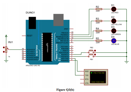
Figure Q3(b) shows the circuit diagram setup of a program to execute simple running lights and potentiometer reading.
There are FOUR (4) LEDs for running lights are and TWO (2) push buttons for interrupts.
In the running lights task (main program), each LED is turned on for 150ms and turned off for another 150ms, consecutively from LED1 (D1) to LED4 (D4).
On the other hand, push button 1 (PB1) is used to trigger Interrupt Program 1 which is to read potentiometer value and push button 2 (PB2) is used to trigger Interrupt Program 2 which is to turn on all LEDs for 200ms and turn them off afterwards.
Develop the programming code to execute required program.
Step by Step Solution
There are 3 Steps involved in it
Step: 1

Get Instant Access to Expert-Tailored Solutions
See step-by-step solutions with expert insights and AI powered tools for academic success
Step: 2

Step: 3
Ace Your Homework with AI
Get the answers you need in no time with our AI-driven, step-by-step assistance
Get Started