

Question: For a water process shown in the figure below, there are two flows that enter into an isothermal stirred tank. For this process, your colleague
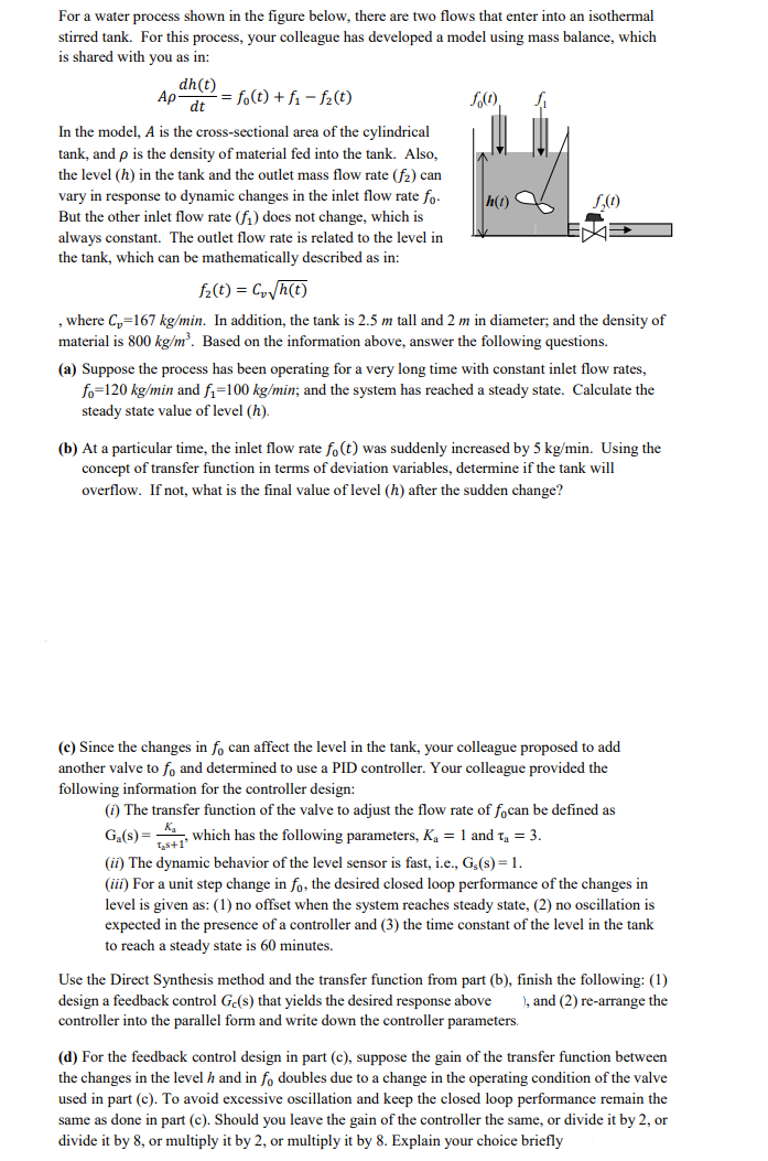
For a water process shown in the figure below, there are two flows that enter into an isothermal stirred tank. For this process, your colleague has developed a model using mass balance, which is shared with you as in: Adtdh(t)=f0(t)+f1f2(t) In the model, A is the cross-sectional area of the cylindrical tank, and is the density of material fed into the tank. Also, the level (h) in the tank and the outlet mass flow rate (f2) can vary in response to dynamic changes in the inlet flow rate f0. But the other inlet flow rate (f1) does not change, which is always constant. The outlet flow rate is related to the level in the tank, which can be mathematically described as in: f2(t)=Cvh(t) , where Cv=167kg/min. In addition, the tank is 2.5m tall and 2m in diameter; and the density of material is 800kg/m3. Based on the information above, answer the following questions. (a) Suppose the process has been operating for a very long time with constant inlet flow rates, f0=120kg/min and f1=100kg/min; and the system has reached a steady state. Calculate the steady state value of level (h) (b) At a particular time, the inlet flow rate f0(t) was suddenly increased by 5kg/min. Using the concept of transfer function in terms of deviation variables, determine if the tank will overflow. If not, what is the final value of level (h) after the sudden change? (c) Since the changes in f0 can affect the level in the tank, your colleague proposed to add another valve to f0 and determined to use a PID controller. Your colleague provided the following information for the controller design: (i) The transfer function of the valve to adjust the flow rate of f0 can be defined as Ga(s)=as+1Ka, which has the following parameters, Ka=1 and a=3. (ii) The dynamic behavior of the level sensor is fast, i.e., Gs(s)=1. (iii) For a unit step change in f0, the desired closed loop performance of the changes in level is given as: (1) no offset when the system reaches steady state, (2) no oscillation is expected in the presence of a controller and (3) the time constant of the level in the tank to reach a steady state is 60 minutes. Use the Direct Synthesis method and the transfer function from part (b), finish the following: (1) design a feedback control Gc(s) that yields the desired response above i, and (2) re-arrange the controller into the parallel form and write down the controller parameters. (d) For the feedback control design in part (c), suppose the gain of the transfer function between the changes in the level h and in f0 doubles due to a change in the operating condition of the valve used in part (c). To avoid excessive oscillation and keep the closed loop performance remain the same as done in part (c). Should you leave the gain of the controller the same, or divide it by 2 , or divide it by 8 , or multiply it by 2 , or multiply it by 8 . Explain your choice briefly
Step by Step Solution
There are 3 Steps involved in it

Get step-by-step solutions from verified subject matter experts