

Answered step by step
Verified Expert Solution
Question
1 Approved Answer
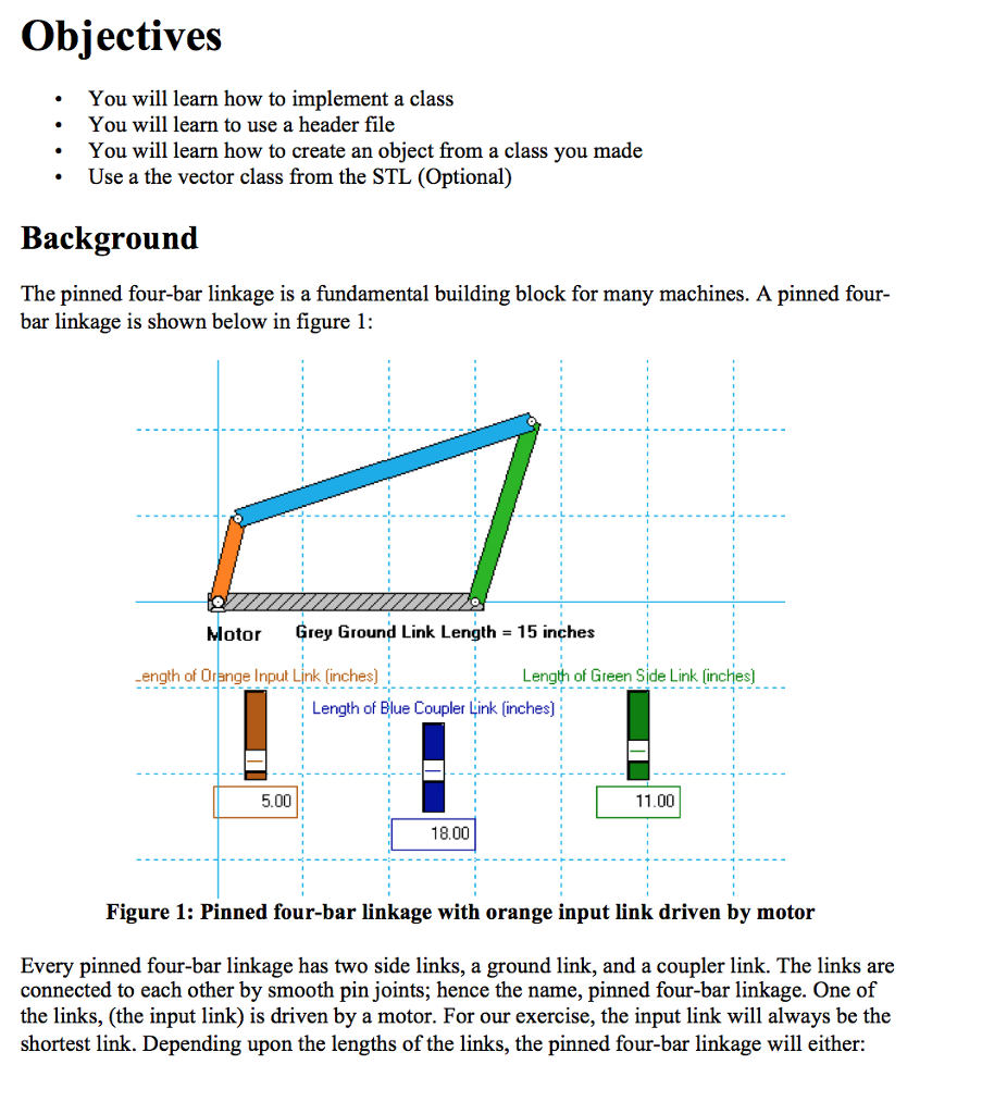
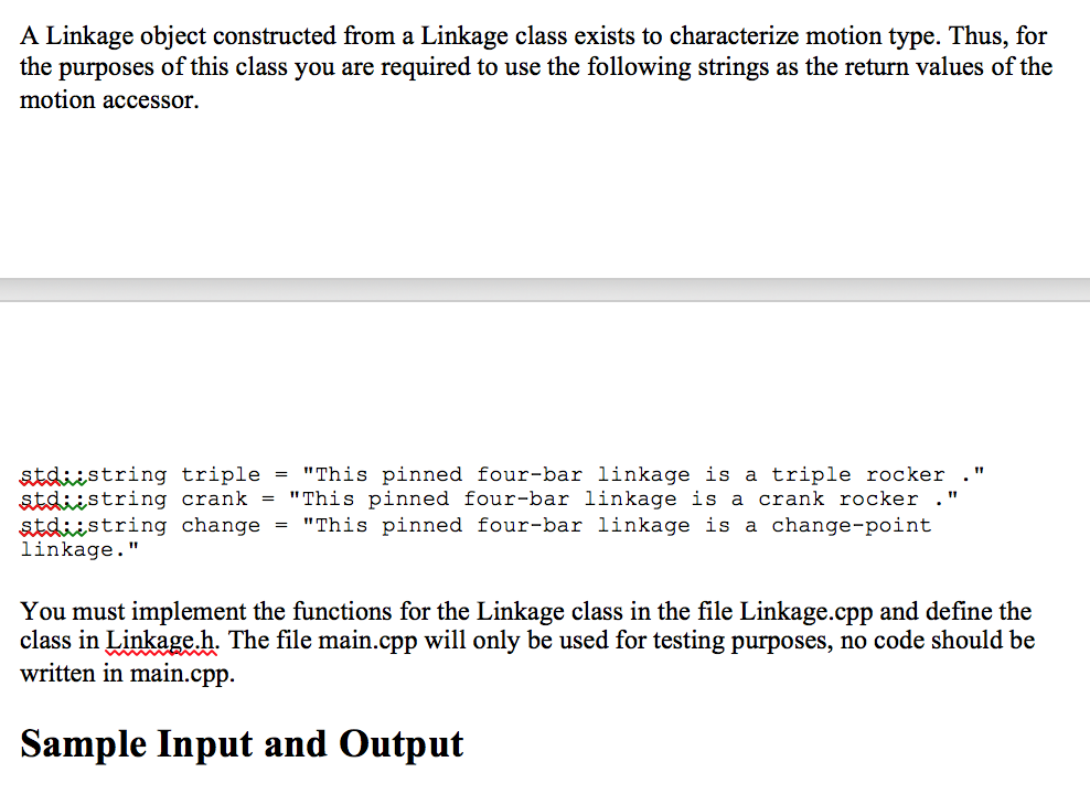
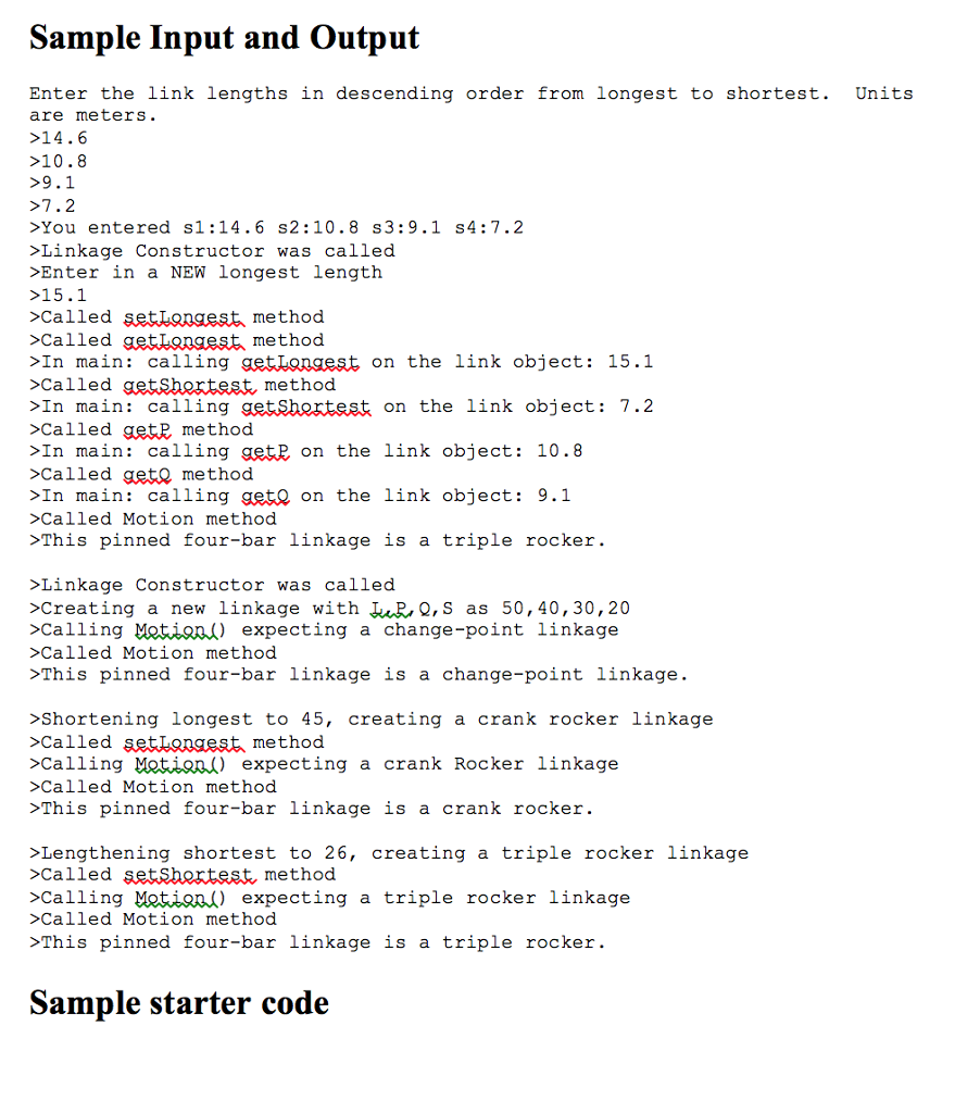
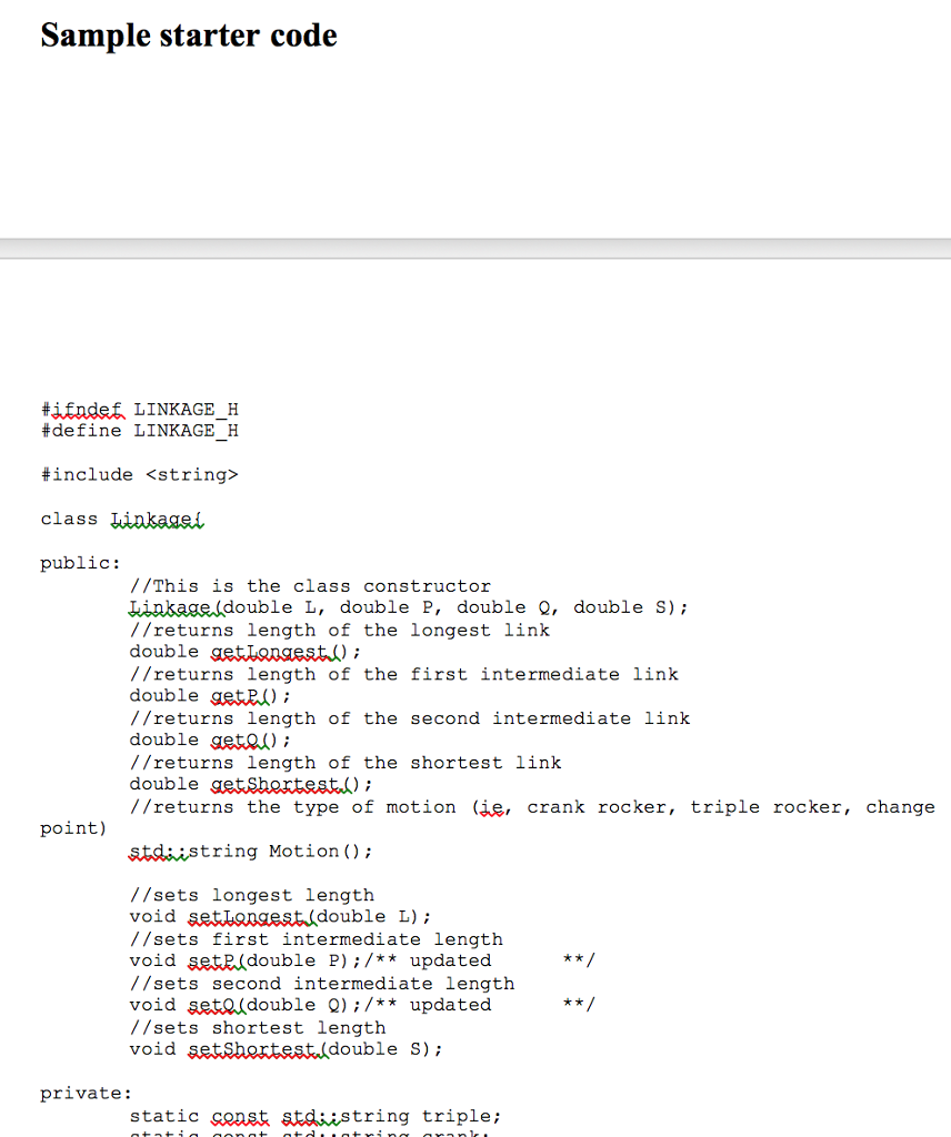
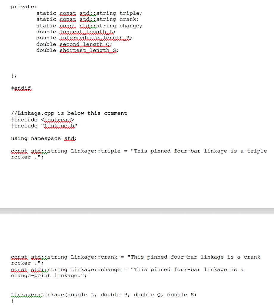
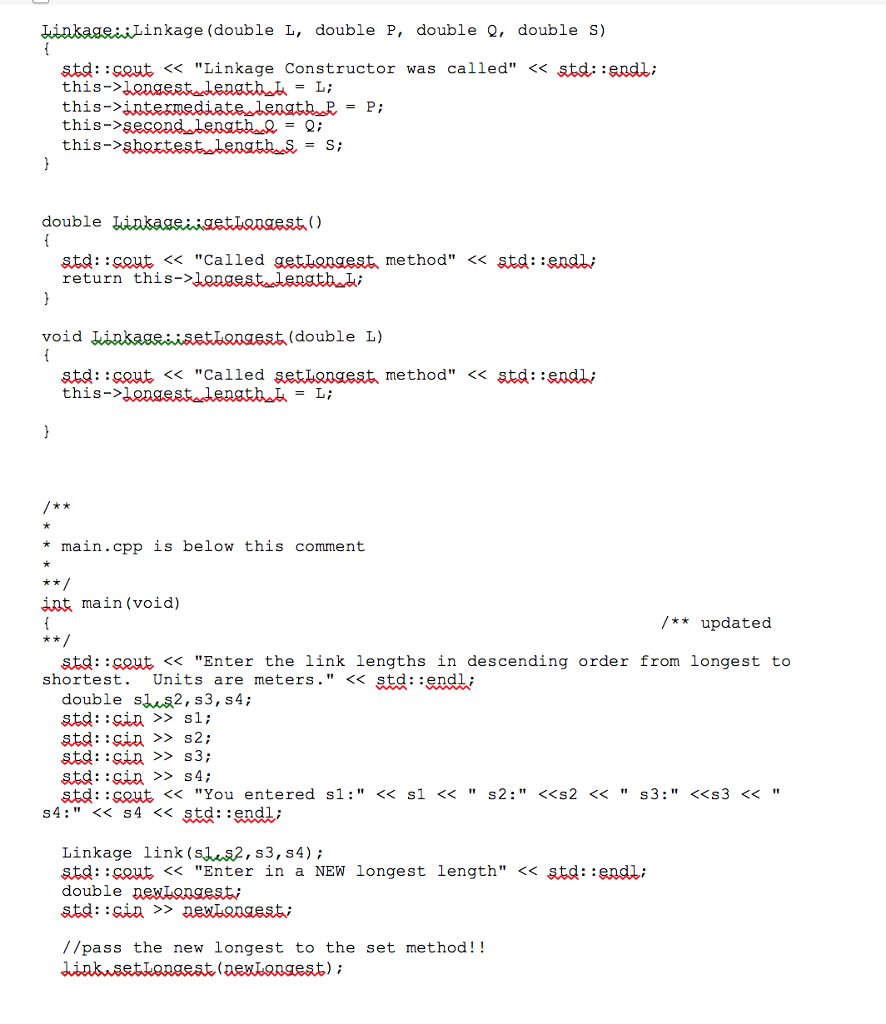
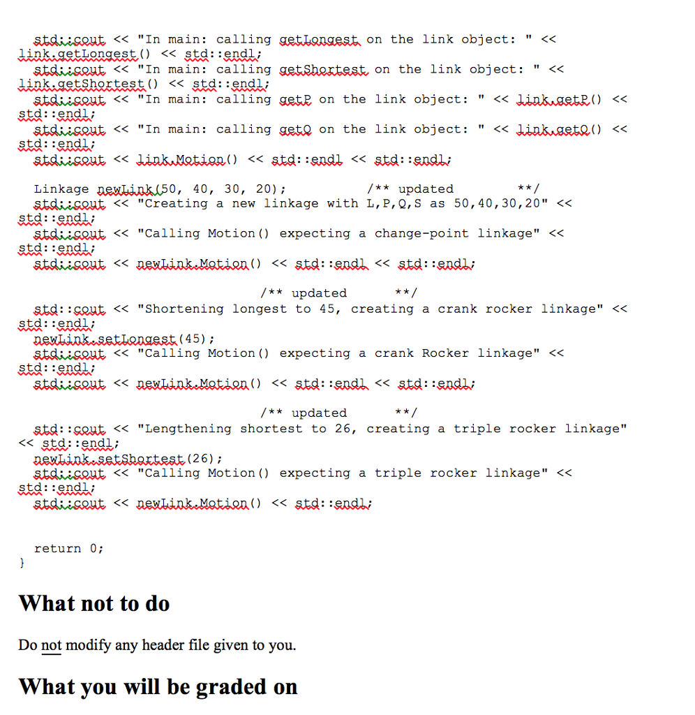
Objectives You will learn how to implement a class You will learn to use a header file You will learn how to create an object
Step by Step Solution
There are 3 Steps involved in it
Step: 1

Get Instant Access to Expert-Tailored Solutions
See step-by-step solutions with expert insights and AI powered tools for academic success
Step: 2

Step: 3
Ace Your Homework with AI
Get the answers you need in no time with our AI-driven, step-by-step assistance
Get Started
Database And Expert Systems Applications 31st International Conference Dexa 2020 Bratislava Slovakia September 14 17 2020 Proceedings Part 1 Lncs 12391
Authors: Sven Hartmann ,Josef Kung ,Gabriele Kotsis ,A Min Tjoa ,Ismail Khalil
1st Edition