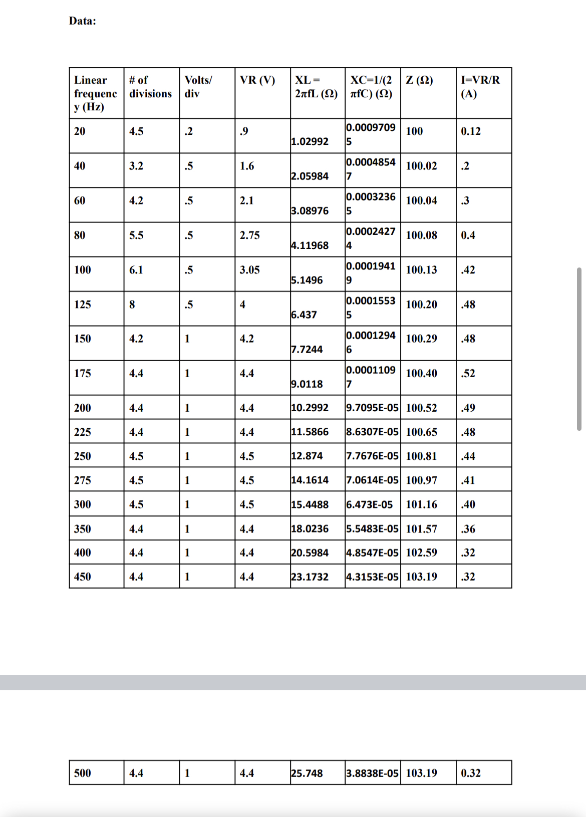
Question: Please use the data I provided to Plot a graph of the voltage across the resistor, VR (vertical axis) vs. frequency, f (horizontal axis). determine
Please use the data I provided to
Plot a graph of the voltage across the resistor, VR (vertical axis) vs. frequency, f (horizontal axis). determine the inductive reactance, capacitive reactance, total impedance and the amplitude of the current through the resistor
then plot XL, XC and Z vs. frequency.
Please create graphs digitally and not on paper


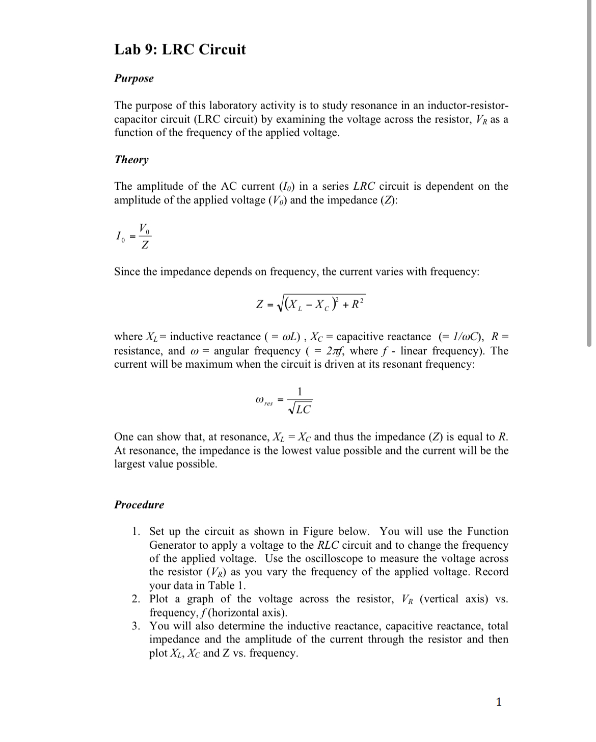
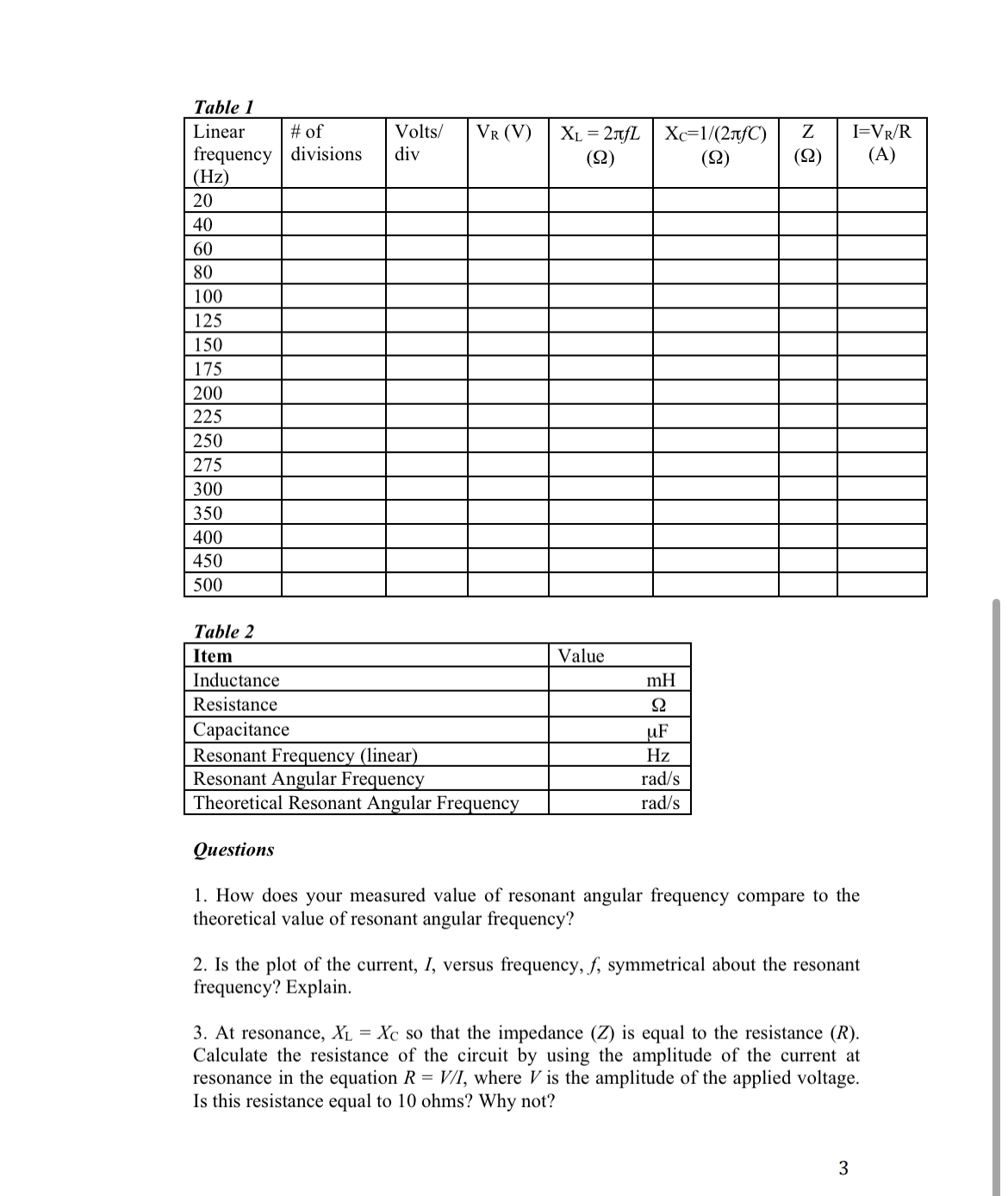
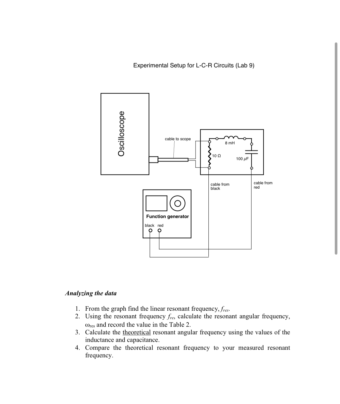
Lab 9: LRC Circuit Purpose The purpose of this laboratory activity is to study resonance in an inductor-resistor- capacitor circuit (LRC circuit) by examining the voltage across the resistor, VR as a function of the frequency of the applied voltage. Theory The amplitude of the AC current (In) in a series LRC circuit is dependent on the amplitude of the applied voltage (Va) and the impedance (Z): V0 0'? Since the impedance depends on frequency, the current varies with frequency: Z=,/()r,X,,)2 +R2 where XL = inductive reactance ( = coL) , X5 = capacitive reactance (= I/mC), R = resistance, and to = angular frequency ( = 279\Table 1 Linear # of Volts! VR (V) XL = 2391 Xc=1f(2:ij) Z I=VRFR frequency divisions div (9) (Q) (Q) (A) Hz _____-_ _____-_ E_____-_ E_____-_ _____-_ _____-_ [Iii-__-_ _____-_ _____-_ _____-_ _____-_ _____-_ _____-_ _____-_ _____-_ Resistance '1 Questions 1. How does y0ur measured value of resonant angular frequency compare to the theoretical value of resonant angular frequency? 2. Is the plot of the current, I, versus frequency, f, symmetrical about the resonant frequency? Explain. 3. At resonance, XL = Xc so that the impedance (Z) is equal to the resistance (R). Calculate the resistance of the circuit by using the amplitude of the current at resonance in the equation R = V/I, where V is the amplitude of the applied voltage. Is this resistance equal to 10 ohms? Why not? Data: Linear # of Volts/ VR (V) XL = XC=1/(2 Z (2) I=VR/R frequenc divisions div 2nfL (2) ItfC) (2) (A) y (Hz) 20 4.5 .2 .9 0.0009709 100 0.12 1.02992 5 40 3.2 .5 1.6 0.0004854 100.02 .2 2.05984 7 60 4.2 .5 2.1 0.0003236 100.04 3 3.08976 5 80 5.5 .5 2.75 0.0002427 100.08 0.4 4.11968 4 100 6.1 .5 3.05 0.0001941 100.13 42 5.1496 125 8 .5 0.0001553 100.20 .48 6.437 5 150 4.2 1 4.2 0.0001294 100.29 .48 7.7244 6 175 4.4 4.4 0.0001109 100.40 52 9.0118 200 4.4 1 4.4 10.2992 9.7095E-05 100.52 49 225 4.4 1 4.4 11.5866 8.6307E-05 100.65 48 250 4.5 4.5 12.874 7.7676E-05 100.81 44 275 4.5 4.5 14.1614 7.0614E-05 100.97 41 300 4.5 4.5 15.4488 6.473E-05 101.16 .40 350 4.4 4.4 18.0236 5.5483E-05 101.57 36 400 4.4 4.4 20.5984 4.8547E-05 102.59 .32 450 4.4 4.4 23.1732 4.3153E-05 103.19 .32 500 4.4 1 4.4 25.748 3.8838E-05 103.19 0.32Experimental Setup for L-C-FI Circuits (Lab 9) cable to scope ._J! E Function generator Oscilloscope cable from cable from red black red Analyzing the data 1. From the graph nd the linear resonant frequency, fm. 2. Using the resonant frequency e, calculate the resonant angular frequency, (res and record the value in the Table 2. 3. Calculate the theoretical resonant angular frequency using the values of the inductance and capacitance. 4. Compare the theoretical resonant frequency to your measured resonant frequency. Item Value Inductance mH Resistance Capacitance UF Resonant Frequency (linear) Hz Resonant Angular Frequency rad/s Theoretical Resonant Angular Frequency rad/s
Step by Step Solution
There are 3 Steps involved in it

Get step-by-step solutions from verified subject matter experts


