Question: RC Circuits (Resistor and Capacitor) Equipment: 1. 850 Universal Interface 2. Resistor/Capacitor/Inductor Network 3. Voltage sensor 4. Banana Plug Cord Sets Setup 1. Construct the
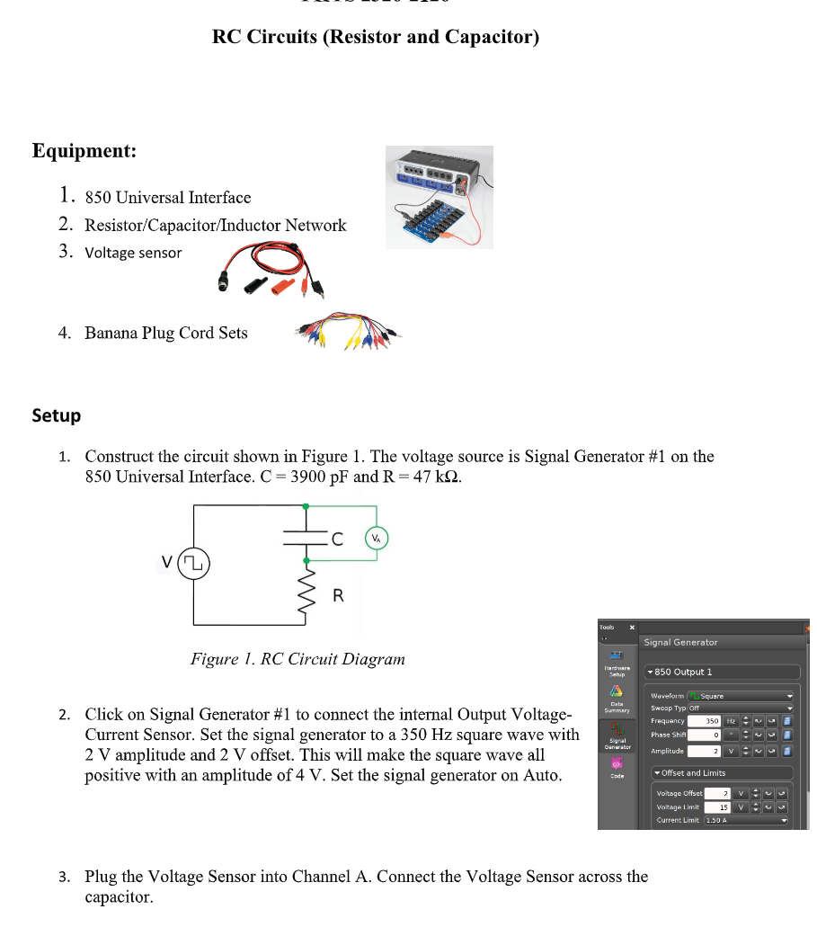
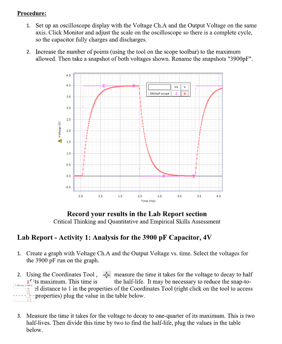
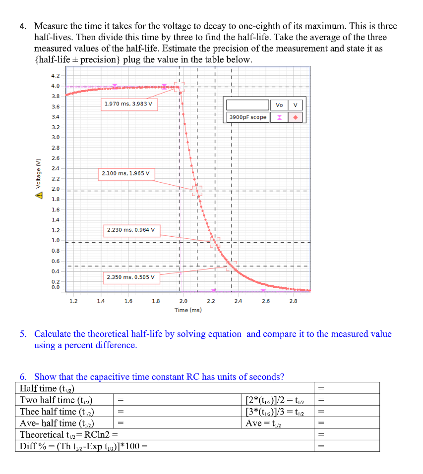
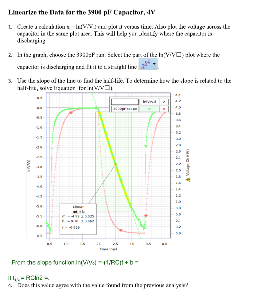
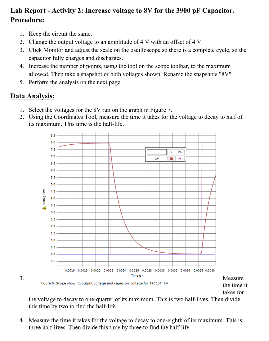
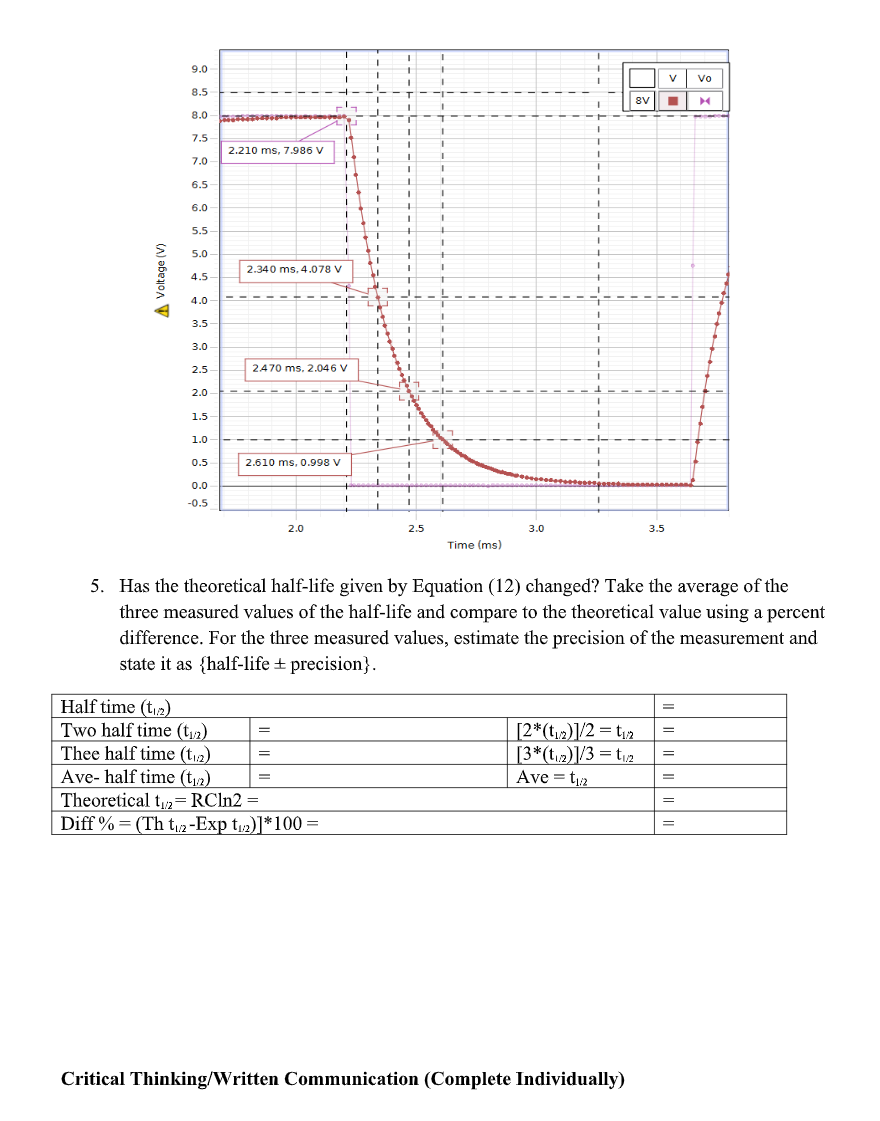
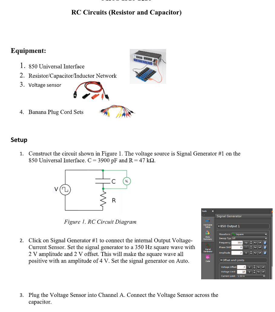
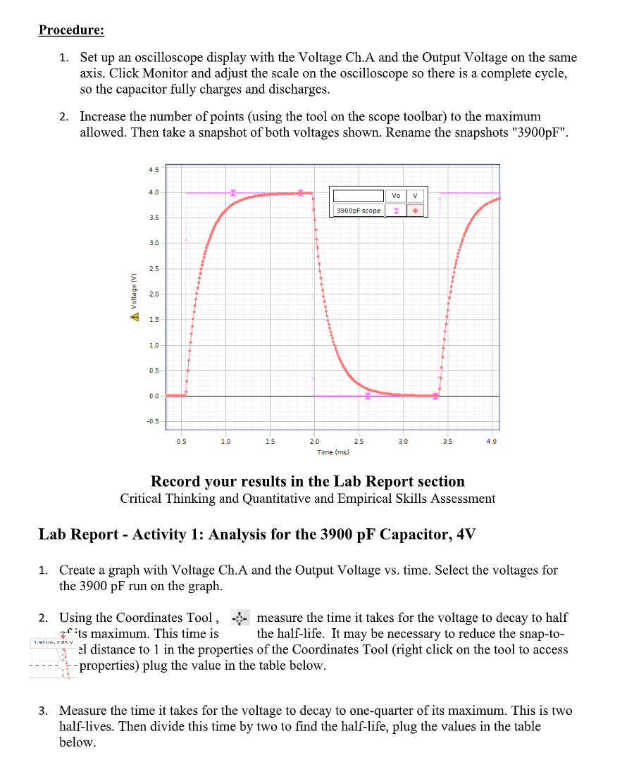
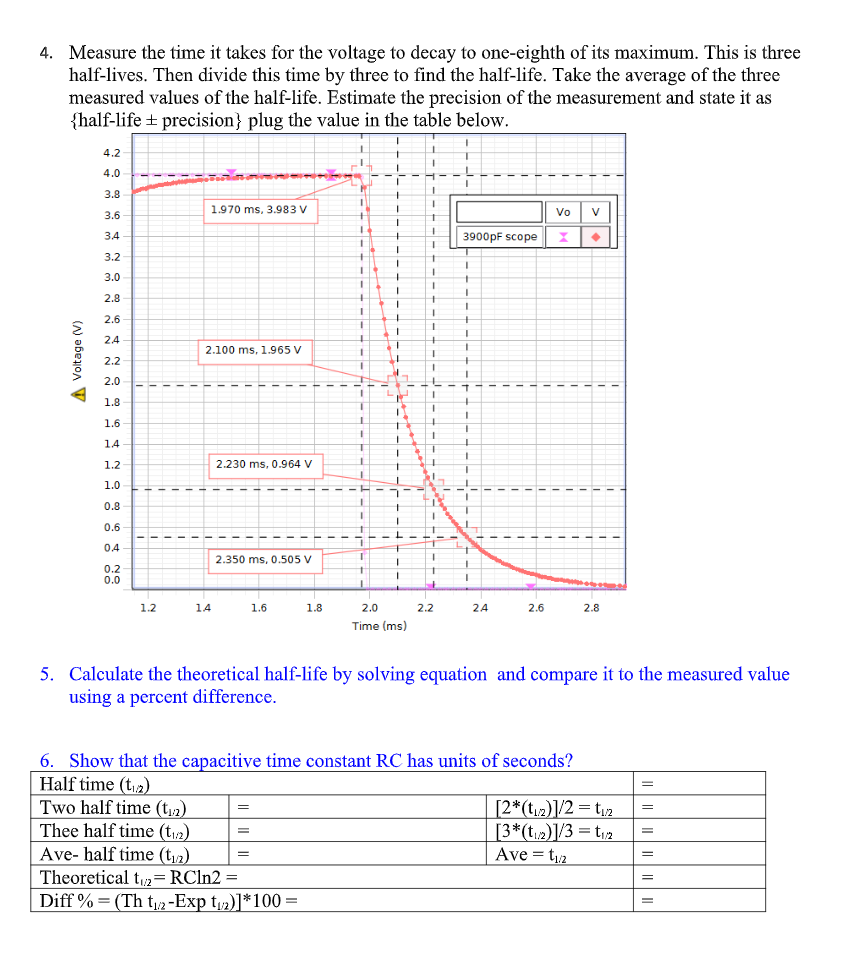
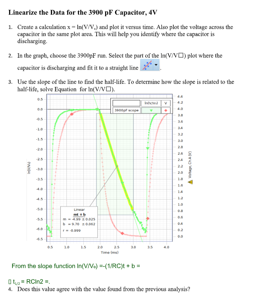
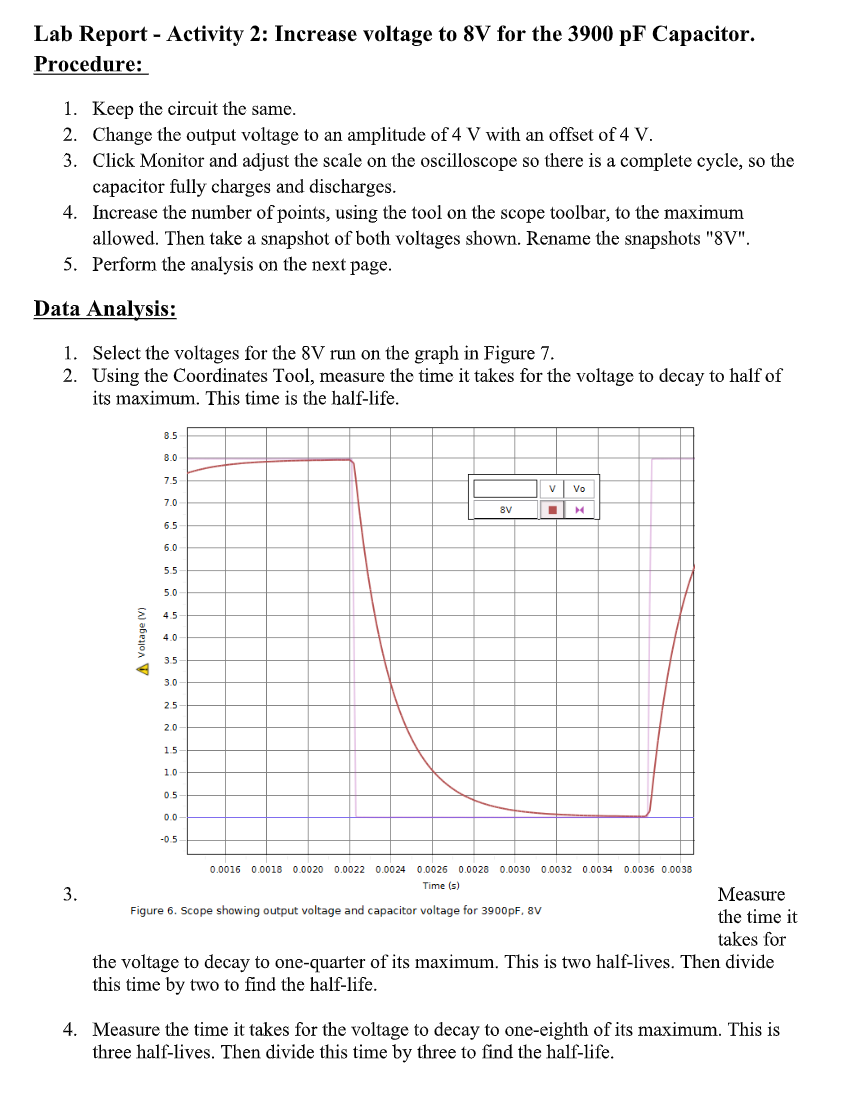
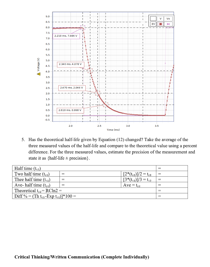
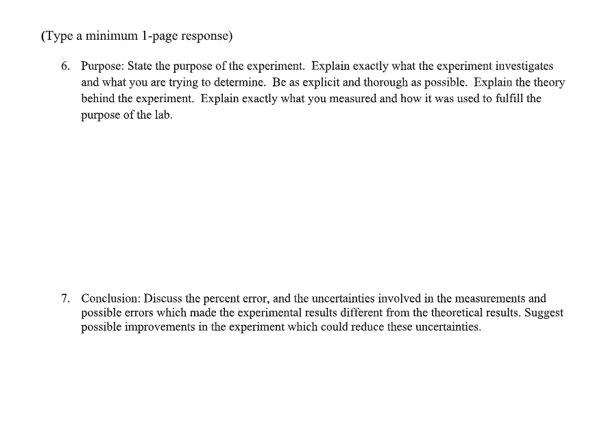
RC Circuits (Resistor and Capacitor) Equipment: 1. 850 Universal Interface 2. Resistor/Capacitor/Inductor Network 3. Voltage sensor 4. Banana Plug Cord Sets Setup 1. Construct the circuit shown in Figure 1. The voltage source is Signal Generator #1 on the 850 Universal Interface. C = 3900 pF and R = 47 kQ. R Tools X Signal Generator Figure I. RC Circuit Diagram 850 Output 1 A Waveform (4 Square 2. Click on Signal Generator #1 to connect the internal Output Voltage- Sweep Typ Off Frequency 350 Current Sensor. Set the signal generator to a 350 Hz square wave with Phase Ship 2 V amplitude and 2 V offset. This will make the square wave all Amplitud positive with an amplitude of 4 V. Set the signal generator on Auto. Offset and Limits Voltage Offset Voltage Limit 15 V Current Limit (1.50 A 3. Plug the Voltage Sensor into Channel A. Connect the Voltage Sensor across the capacitor.Procedure: 1. Set up an oscilloscope display with the Voltage ChA and the Output Voltage on the saute axis. Click Monitor and adjust the scale on the oscilloscope so there is a complete cycle, so the capacitor fully charges and discharges. 2. Increase the number of points (using the tool on the scope toolbar} to the maximum allowed. Then take a snapshot of both voltages shown. Rename the snapshots "3900pF". - . :I t. | v _, 1 3EEIDpF scope I + 4. 4 3' J O i' ' f : '. f L. f d5 GB 3.5 3.0 I 5 .o o 2.5 2.0 35 Voltage- M 1.5 In US DD D5 ISLE LEI 1.5 2.0 2 5 3- C 3.5 4.0 'nme his} Record your results in the Lab Report section Critical Thinking and Quantitative and Empirical Skills Assossmcut Lab Report - Activity 1: Analysis for the 3900 pF Capacitor, 4V 1. Create a graph with Voltage Chit. and the Output Voltage vs. time. Select the voltages for the 3900 pF run on the graph. 2. Using the Coordinates Tool , -:::- measure the time it takes for the voltage to decayr to half __ ft" its maximum. This time is the half-life. It may be necessary to reduce the snap-to- 1mm: 9 :1 distance to 1 in the properties of the Coordinates Tool (right click on the tool to access ----- :2: - properties) plug the value in the table below. 3. Measure the time it takes for the voltage to decay,r to onequarter of its maximum. This is two half-lives. Then divide this time by two to nd the half-life, plug the values in the table below. 4. Measure the time it takes for the voltage to decay to one-eighth of its maximum. This is three half-lives. Then divide this time by three to find the half-life. Take the average of the three measured values of the half-life. Estimate the precision of the measurement and state it as (half-life + precision} plug the value in the table below. 4.2 4.0 3.8 3.6 1.970 ms. 3.983 V Vo 3.4 3900pF scope 3.2 3.0 2.8 2.6 24 Voltage (V) 2.100 ms, 1.965 V 2.2 2.0 1.8 1.6 14 1.2 2.230 ms, 0.964 V 1.0 0.8 0.6 0.4 2.350 ms, 0.505 V 0.2 0.0 1.2 14 1.6 1.8 2.0 2.2 24 2.6 2.8 Time (ms) 5. Calculate the theoretical half-life by solving equation and compare it to the measured value using a percent difference. 6. Show that the capacitive time constant RC has units of seconds? Half time (tizz) = Two half time (tuz) 11 [2*(t12)]/2 = t12 11 Thee half time (12) [3*(t12)]/3 = 12 = Ave- half time (tiz) = Ave = t12 = Theoretical t12= RCIn2 = 11 Diff % = (Th tizz-Exp ti2)]*100 = =Linearize the Data for the 3900 pF Capacitor, 4V 1. Create a calculation x = In(V/V.) and plot it versus time. Also plot the voltage across the capacitor in the same plot area. This will help you identify where the capacitor is discharging. 2. In the graph, choose the 3900pF run. Select the part of the In(V/VO) plot where the capacitor is discharging and fit it to a straight line 3. Use the slope of the line to find the half-life. To determine how the slope is related to the half-life, solve Equation for In(V/VO). 4 A 0.5 In(V/Vo) V 4.2 0.0 3900pF scope 4.0 3.8 -0.5 3.6 -1.0 34 3.2 -1.5 3.0 -2.0 2.8 2.6 -2.5 A Voltage, ChA(V) In(V/Vo) -3.0 3.5 4.0 4.5 -5.0 Linear mt + b -5.5 m = 4.99 0.025 b - 9.70 = 0.062 -6.0 r = -0.999 0.2 0.0 0.5 1.0 1.5 2.0 2.5 3.0 3.5 4.0 Time (ms) From the slope function In(V/Vo) =-(1/RC)t + b = 0 t1/2 = RCIn2 =. 4. Does this value agree with the value found from the previous analysis?Lab Report - Activity 2: Increase voltage to 3V for the 3900 pF Capacitor. Procedure: 1. Keep the circuit the same. lChange the output voltage to an amplitude of 4 V with an offset of 4 'v'. 3. Click Monitor and adjust the scale on the oscilloscope so there is a complete cycle, so the capacitor fully charges and discharges. 4. Increase the number of points, using the tool on the scope toolbar, to the maximum allowed. Then take a snapshot of both voltages shown. Rename the snapshots "8V". 5. Perfonn the analysis on the next page. Data Analysis: 1. Select the voltages for the 8'! run on the graph in Figure 3'. 2. Using the Coordinates Tool, measure the time it takes for the voltage to decay to half of its maximum. This time is the half-life. :0. Voltage w] 0.0015 00013 00020 0.0022 0.0024 000.26 00020 00030 0.003.! 00034 0003-5 0003-3- Tlme [5] 3 Measure Figure 5. Scope showing output voltage and capacitor voltage For 39:10pm. av the time it takes for the voltage to decay to onequarter of its maximum. This is two halflives. Then divide this time by two to nd the half-life. 4. Measure the time it takes for the voltage to decay to one-eighth of its maximum. This is three half-lives. Then divide this time by three to nd the half-life. 9.0 V Vo 8.5 8V 8.0 7.5 2.210 ms, 7.986 V 7.0 6.5 6.0 5.5 5.0 Voltage (V) 4.5 2.340 ms, 4.078 V 4.0 3.5 3.0 2.5 2.470 ms. 2.046 V 2.0 1.5 1.0 0.5 2.610 ms, 0.998 V 0.0 -0.5 2.0 2.5 3.0 3.5 Time (ms) 5. Has the theoretical half-life given by Equation (12) changed? Take the average of the three measured values of the half-life and compare to the theoretical value using a percent difference. For the three measured values, estimate the precision of the measurement and state it as {half-life + precision}. Half time (t12) Two half time (tiz) [2*(t12)1/2 = t12 11 11 Thee half time (t12) [3*(t12)]/3 = tu2 11 11 11 Ave- half time (t12) Ave = t1/2 Theoretical t,2= RCIn2 = = 11 Diff % = (Th to2-Exp t12)]*100 = Critical Thinking/Written Communication (Complete Individually)(Type a minimum 1page response) 6. Purpose: State the purpose of the experiment. Explain exactly what the experiment investigates and what you are trying to determine. Be as explicit and thorough as possible. Explain the theory behind the experiment. Explain exactly what you measured and how it was used to fulfill the putpose of the lab. 7". Conclusion: Discuss the percent error, and the uncertainties involved in the measurements and possible errors which made the experimental results different from the theoretical results. Suggest possible improvements in the experiment which could reduce these uncertainties
Step by Step Solution
There are 3 Steps involved in it

Get step-by-step solutions from verified subject matter experts


