Question: 11 Appendix Al Equation (1), for the charging capacitor in Procedure A: (1) i(t) = R1 e At t=0s, the current i(0) value is the
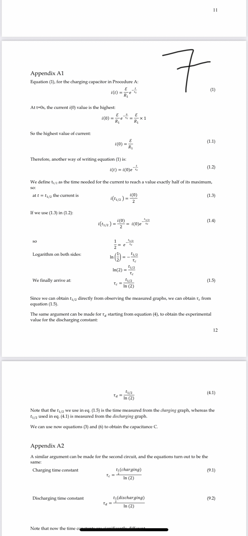
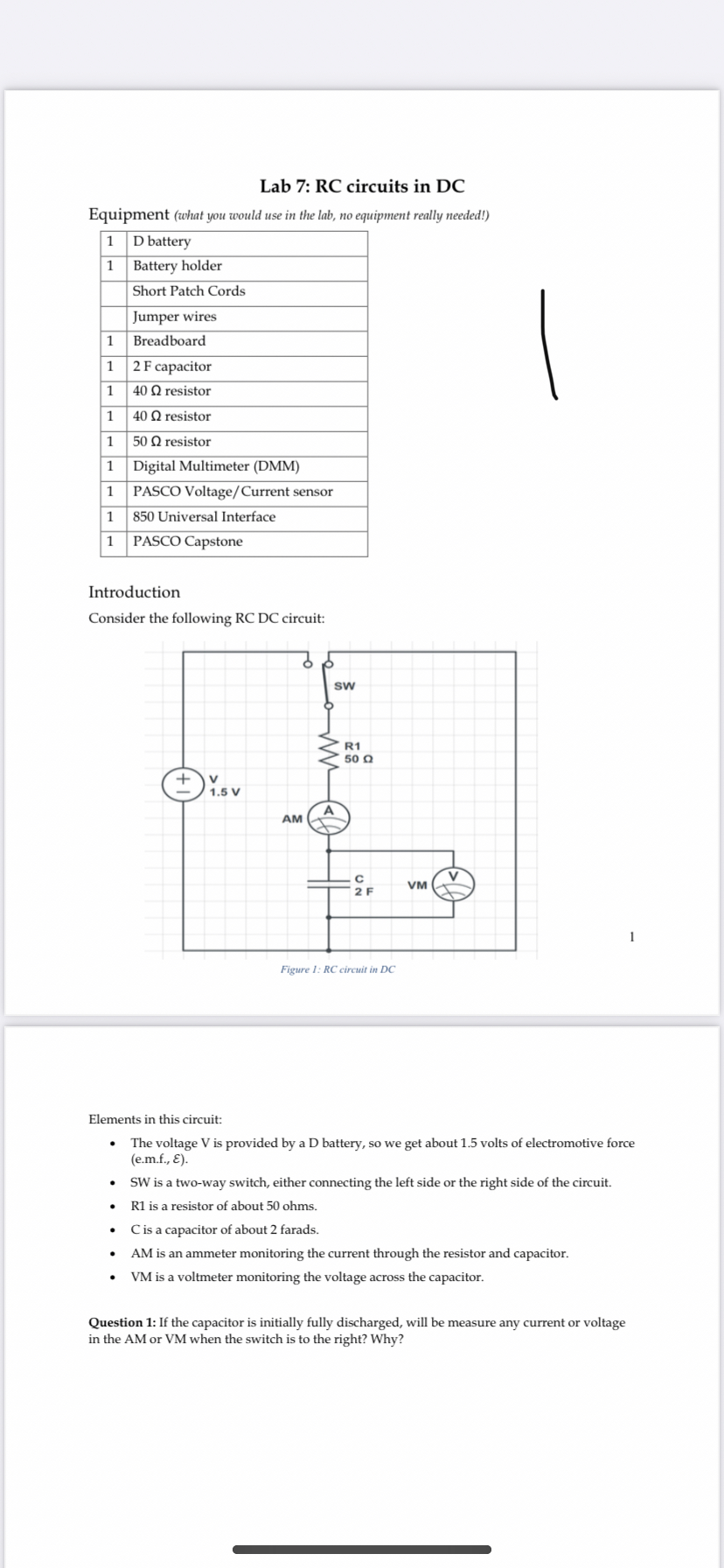
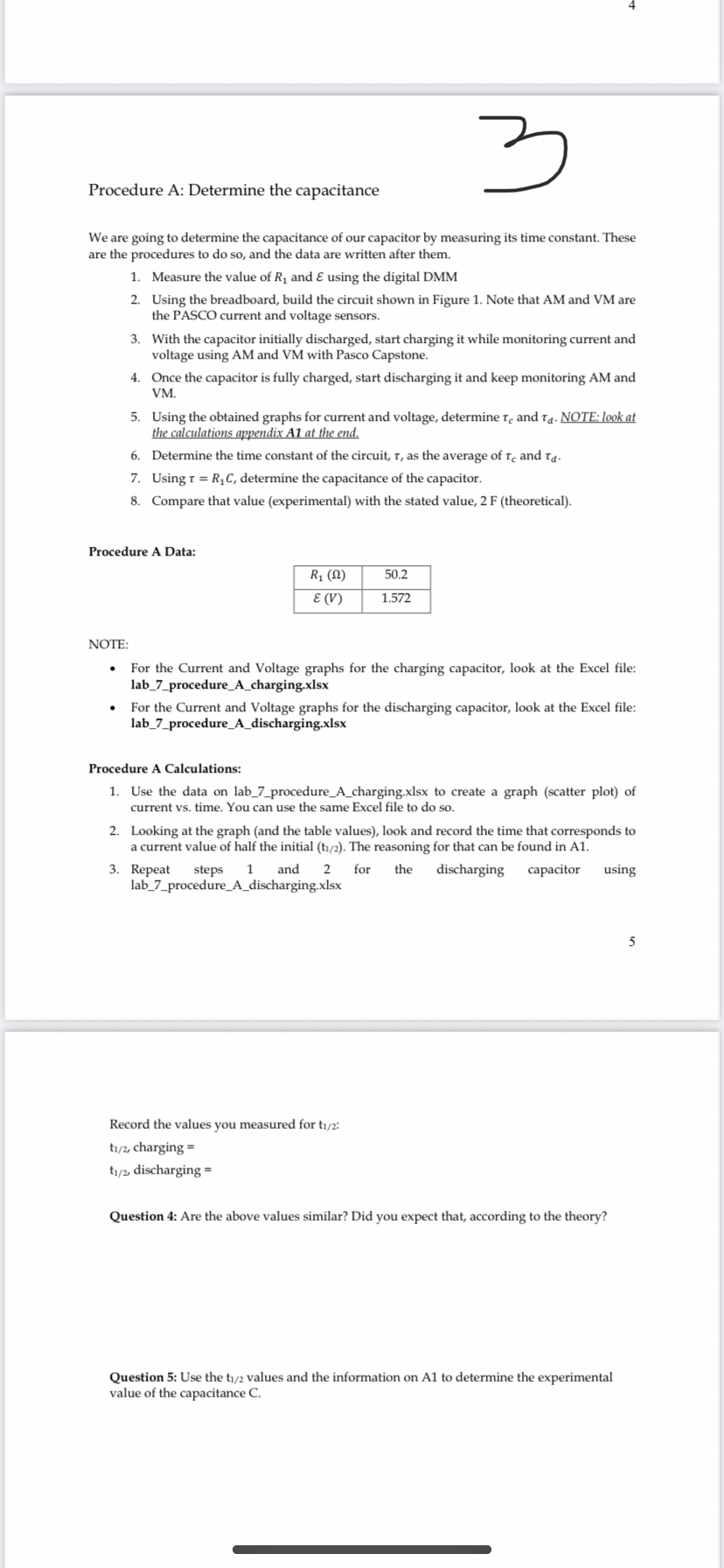
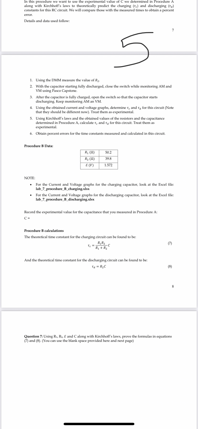
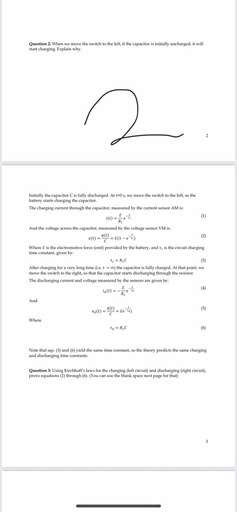
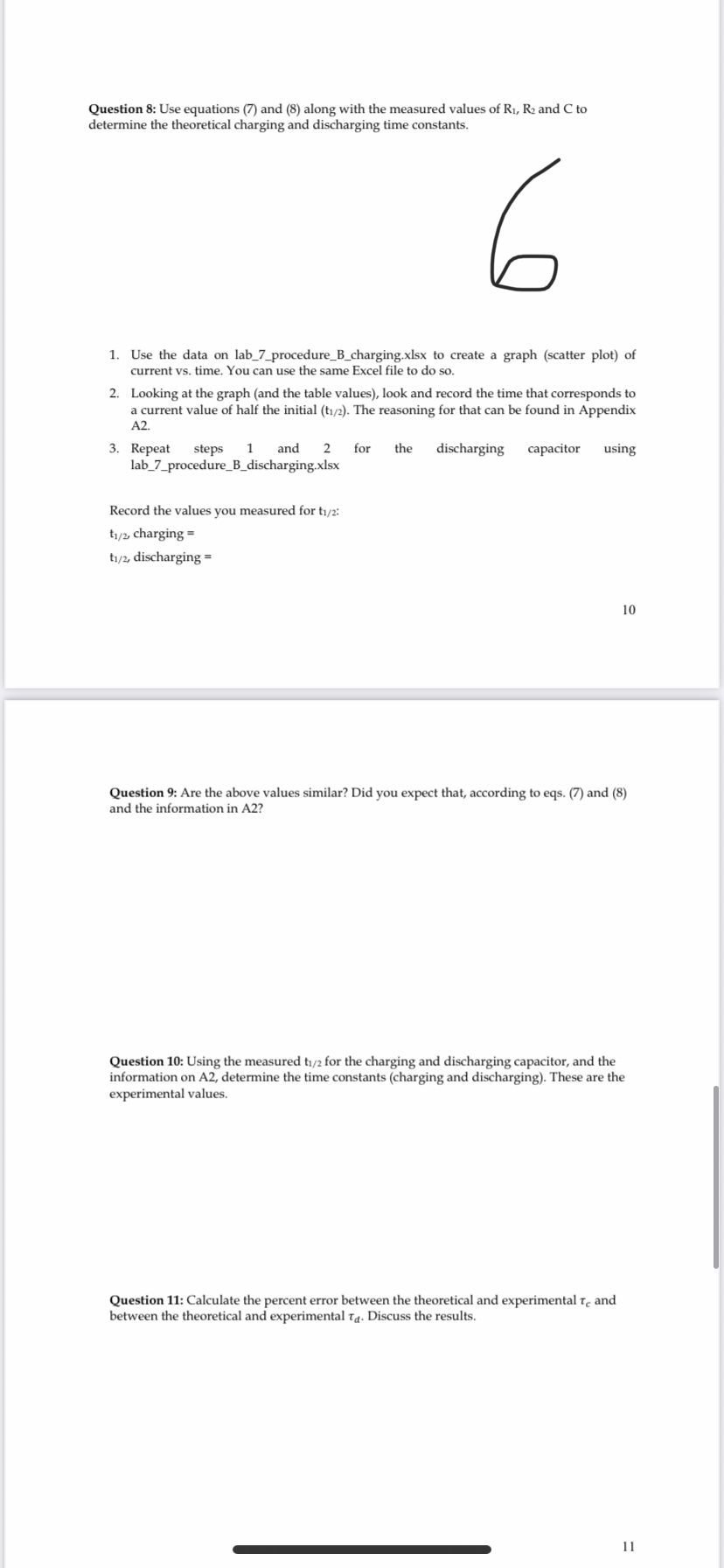
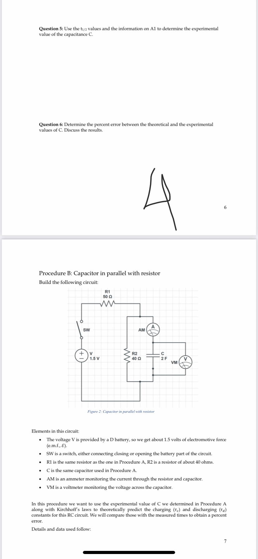
11 Appendix Al Equation (1), for the charging capacitor in Procedure A: (1) i(t) = R1 e At t=0s, the current i(0) value is the highest: (0) = R1 x 1 R1 So the highest value of current: (1.1) i(0) = Ry Therefore, another way of writing equation (1) is: i(t) = i(0)e te (1.2) We define t1/2 as the time needed for the current to reach a value exactly half of its maximum, so: at t = t1/2 the current is - i(0) i(t1/2 ) = = (1.3) 2 If we use (1.3) in (1.2): (1.4) i(t1/2 ) = 2 10 = i(0)e te 50 NIP = e te Logarithm on both sides: In () $1/2 Ic In(2) = t1/2 Ic We finally arrive at: $1/2 (1.5 In (2) Since we can obtain t1/2 directly from observing the measured graphs, we can obtain to from equation (1.5). The same argument can be made for to starting from equation (4), to obtain the experimental value for the discharging constant: 12 t1/2 (4.1) Td In (2) Note that the t1/2 we use in eq. (1.5) is the time measured from the charging graph, whereas the 1/2 used in eq. (4.1) is measured from the discharging graph. We can use now equations (3) and (6) to obtain the capacitance C. Appendix A2 A similar argument can be made for the second circuit, and the equations turn out to be the same: Charging time constant ti (charging) (9.1) In (2) Discharging time constant ti(discharging) (9.2) Id = = In (2) Note that now the time cLab 7: RC circuits in DC Equipment (what you would use in the lab, no equipment really needed!) 1 D battery 1 Battery holder Short Patch Cords Jumper wires 1 Breadboard 1 2 F capacitor 1 40 0 resistor 1 40 0 resistor 1 50 Q resistor 1 Digital Multimeter (DMM) 1 PASCO Voltage/ Current sensor 1 850 Universal Interface 1 PASCO Capstone Introduction Consider the following RC DC circuit: SW R1 50 Q + 1.5 V AM C 2 F VM Figure 1: RC circuit in DC Elements in this circuit: The voltage V is provided by a D battery, so we get about 1.5 volts of electromotive force (e.m.f., 8). SW is a two-way switch, either connecting the left side or the right side of the circuit. R1 is a resistor of about 50 ohms. C is a capacitor of about 2 farads. AM is an ammeter monitoring the current through the resistor and capacitor. VM is a voltmeter monitoring the voltage across the capacitor. Question 1: If the capacitor is initially fully discharged, will be measure any current or voltage in the AM or VM when the switch is to the right? Why?2 Procedure A: Determine the capacitance We are going to determine the capacitance of our capacitor by measuring its time constant. These are the procedures to do so, and the data are written after them. 1. Measure the value of R, and & using the digital DMM 2. Using the breadboard, build the circuit shown in Figure 1. Note that AM and VM are the PASCO current and voltage sensors. 3. With the capacitor initially discharged, start charging it while monitoring current and voltage using AM and VM with Pasco Capstone. 4. Once the capacitor is fully charged, start discharging it and keep monitoring AM and VM. 5. Using the obtained graphs for current and voltage, determine re and Ta. NOTE: look at the calculations appendix A1 at the end. 6. Determine the time constant of the circuit, r, as the average of To and Ta. 7. Using T = R, C, determine the capacitance of the capacitor. 8. Compare that value (experimental) with the stated value, 2 F (theoretical). Procedure A Data: R 1 (2 ) 50.2 E (V) 1.572 NOTE: For the Current and Voltage graphs for the charging capacitor, look at the Excel file: lab_7_procedure_A_charging.xIsx For the Current and Voltage graphs for the discharging capacitor, look at the Excel file: lab_7_procedure_A_discharging.xlsx Procedure A Calculations: 1. Use the data on lab_7_procedure_A_charging.xlsx to create a graph (scatter plot) of current vs. time. You can use the same Excel file to do so. 2. Looking at the graph (and the table values), look and record the time that corresponds to a current value of half the initial (ti/2). The reasoning for that can be found in Al. 3. Repeat steps 1 and 2 for the discharging capacitor using lab_7_procedure_A_discharging.xlsx 5 Record the values you measured for ti/2: t1/2, charging = t1/2 discharging = Question 4: Are the above values similar? Did you expect that, according to the theory? Question 5: Use the t1/2 values and the information on Al to determine the experimental value of the capacitance C.In this procedure we want to use the experimental value of C we determined in Procedure A along with Kirchhoff's laws to theoretically predict the charging (Te) and discharging (Ta) constants for this RC circuit. We will compare those with the measured times to obtain a percent error. Details and data used follow: 1. Using the DMM measure the value of R2- 2. With the capacitor starting fully discharged, close the switch while monitoring AM and VM using Pasco Capstone. 3. After the capacitor is fully charged, open the switch so that the capacitor starts discharging. Keep monitoring AM an VM. 4. Using the obtained current and voltage graphs, determine re and ta for this circuit (Note that they should be different now). Treat them as experimental. 5. Using Kirchhoff's laws and the obtained values of the resistors and the capacitance determined in Procedure A, calculate To and ta for this circuit. Treat them as experimental. 6. Obtain percent errors for the time constants measured and calculated in this circuit. Procedure B Data: 50.2 R2 (! ) 39.8 E (V) 1.572 NOTE: For the Current and Voltage graphs for the charging capacitor, look at the Excel file: lab_7_procedure_B_charging.xisx For the Current and Voltage graphs for the discharging capacitor, look at the Excel file: lab_7_procedure_B_discharging.xlsx Record the experimental value for the capacitance that you measured in Procedure A: C = Procedure B calculations The theoretical time constant for the charging circuit can be found to be: R1R2 C (7 ) TC R1 + R2 And the theoretical time constant for the discharging circuit can be found to be: Td = R2C (8) 8 Question 7: Using R1, Rz, & and C along with Kirchhoff's laws, prove the formulas in equations (7) and (8). (You can use the blank space provided here and next page)Question 2: When we move the switch to the left, if the capacitor is initially uncharged, it will start charging. Explain why. N Initially the capacitor C is fully discharged. At t=0 s, we move the switch to the left, so the battery starts charging the capacitor. The charging current through the capacitor, measured by the current sensor AM is: i(t) = (1) R1 And the voltage across the capacitor, measured by the voltage sensor VM is: v(t) = 9(6 C = = (1 - e te) (2 ) Where & is the electromotive force (emf) provided by the battery, and To is the circuit charging time constant, given by: Te = RIC (3) After charging for a very long time (i.e. t -+ co) the capacitor is fully charged. At that point, we move the switch to the right, so that the capacitor starts discharging through the resistor. The discharging current and voltage measured by the sensors are given by: la (t) = - (4) R 1 And Va(t) = 90 0= Ee "a) (5) Where [ d = RIC (6) Note that eqs. (3) and (6) yield the same time constant, so the theory predicts the same charging and discharging time constants. Question 3: Using Kirchhoff's laws for the charging (left circuit) and discharging (right circuit), prove equations (1) through (6). (You can use the blank space next page for that) wQuestion 8: Use equations (7) and (8) along with the measured values of R1, R2 and C to determine the theoretical charging and discharging time constants. 1. Use the data on lab_7_procedure_B_charging.xIsx to create a graph (scatter plot) of current vs. time. You can use the same Excel file to do so. 2. Looking at the graph (and the table values), look and record the time that corresponds to a current value of half the initial (t1/2). The reasoning for that can be found in Appendix A2. 3. Repeat steps 1 and 2 for the discharging capacitor using lab_7_procedure_B_discharging.xIsx Record the values you measured for ti/2: t1/2 charging = t1/2, discharging = 10 Question 9: Are the above values similar? Did you expect that, according to eqs. (7) and (8) and the information in A2? Question 10: Using the measured ti/2 for the charging and discharging capacitor, and the information on A2, determine the time constants (charging and discharging). These are the experimental values. Question 11: Calculate the percent error between the theoretical and experimental to and between the theoretical and experimental Ta. Discuss the results. 11Question 5: Use the t1/2 values and the information on Al to determine the experimental value of the capacitance C. Question 6: Determine the percent error between the theoretical and the experimental values of C. Discuss the results. Procedure B: Capacitor in parallel with resistor Build the following circuit: R1 50 0 M SW AM + R2 1.5 V C 40 Q 2 F VM Figure 2: Capacitor in parallel with resistor Elements in this circuit: The voltage V is provided by a D battery, so we get about 1.5 volts of electromotive force (e.m.f., 8). SW is a switch, either connecting closing or opening the battery part of the circuit. . R1 is the same resistor as the one in Procedure A, R2 is a resistor of about 40 ohms. C is the same capacitor used in Procedure A. AM is an ammeter monitoring the current through the resistor and capacitor. VM is a voltmeter monitoring the voltage across the capacitor. In this procedure we want to use the experimental value of C we determined in Procedure A along with Kirchhoff's laws to theoretically predict the charging (Te) and discharging (Ta) constants for this RC circuit. We will compare those with the measured times to obtain a percent error. Details and data used follow: 7
Step by Step Solution
There are 3 Steps involved in it

Get step-by-step solutions from verified subject matter experts


