Answered step by step
Verified Expert Solution
Question
1 Approved Answer
Tank level control pressure The water level control system, seen in Figure 5, is designed to control the level of water in the tank


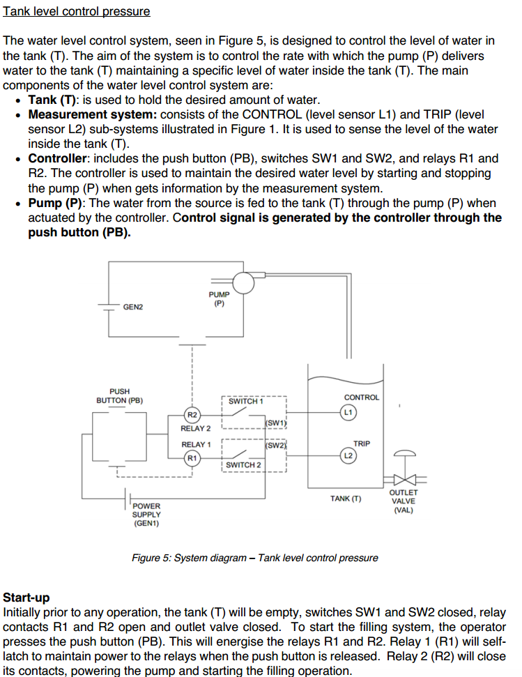
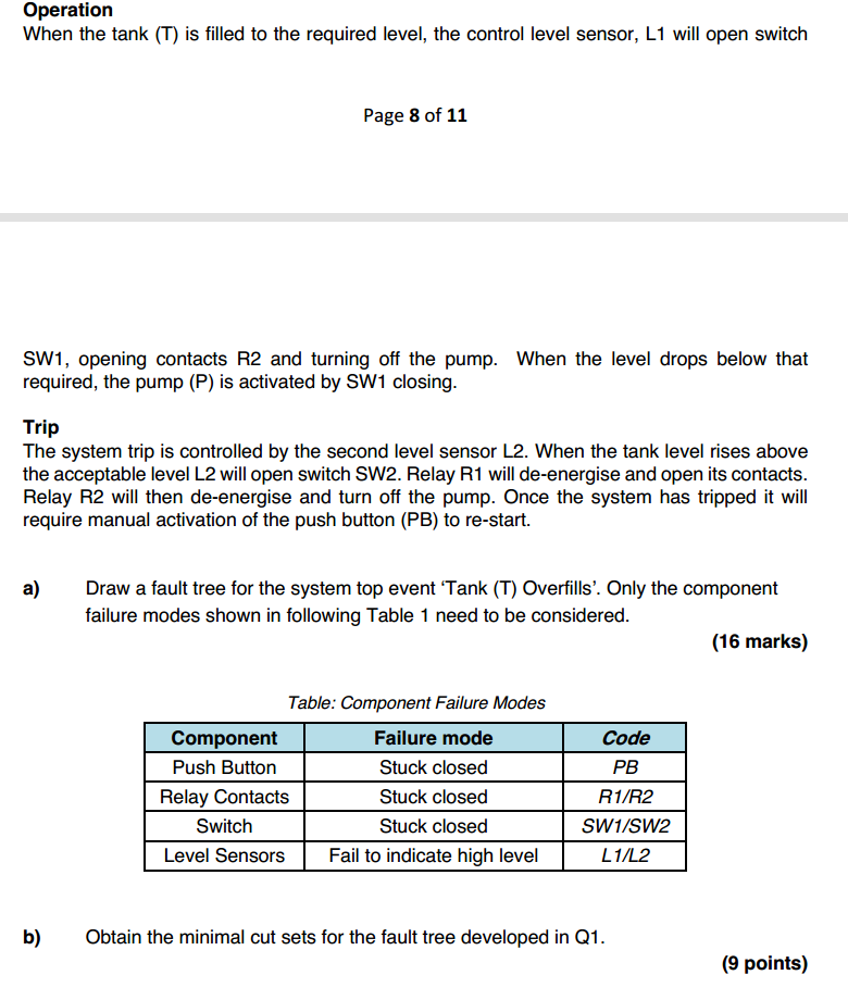
Tank level control pressure The water level control system, seen in Figure 5, is designed to control the level of water in the tank (T). The aim of the system is to control the rate with which the pump (P) delivers water to the tank (T) maintaining a specific level of water inside the tank (T). The main components of the water level control system are: Tank (T): is used to hold the desired amount of water. Measurement system: consists of the CONTROL (level sensor L1) and TRIP (level sensor L2) sub-systems illustrated in Figure 1. It is used to sense the level of the water inside the tank (T). Controller: includes the push button (PB), switches SW1 and SW2, and relays R1 and R2. The controller is used to maintain the desired water level by starting and stopping the pump (P) when gets information by the measurement system. Pump (P): The water from the source is fed to the tank (T) through the pump (P) when actuated by the controller. Control signal is generated by the controller through the push button (PB). GEN2 PUSH BUTTON (PB) POWER SUPPLY (GEN1) PUMP (P) CONTROL SWITCH 1 (SW1) RELAY 2 RELAY 1 (SW2X TRIP SWITCH 2 TANK (T) OUTLET VALVE (VAL) Figure 5: System diagram - Tank level control pressure Start-up Initially prior to any operation, the tank (T) will be empty, switches SW1 and SW2 closed, relay contacts R1 and R2 open and outlet valve closed. To start the filling system, the operator presses the push button (PB). This will energise the relays R1 and R2. Relay 1 (R1) will self- latch to maintain power to the relays when the push button is released. Relay 2 (R2) will close its contacts, powering the pump and starting the filling operation. Operation When the tank (T) is filled to the required level, the control level sensor, L1 will open switch Page 8 of 11 SW1, opening contacts R2 and turning off the pump. When the level drops below that required, the pump (P) is activated by SW1 closing. Trip The system trip is controlled by the second level sensor L2. When the tank level rises above the acceptable level L2 will open switch SW2. Relay R1 will de-energise and open its contacts. Relay R2 will then de-energise and turn off the pump. Once the system has tripped it will require manual activation of the push button (PB) to re-start. a) Draw a fault tree for the system top event 'Tank (T) Overfills'. Only the component failure modes shown in following Table 1 need to be considered. Component Table: Component Failure Modes Failure mode Code Push Button Stuck closed PB Relay Contacts Stuck closed R1/R2 Switch Level Sensors Stuck closed SW1/SW2 Fail to indicate high level L1/L2 (16 marks) b) Obtain the minimal cut sets for the fault tree developed in Q1. (9 points)
Step by Step Solution
There are 3 Steps involved in it
Step: 1

Get Instant Access to Expert-Tailored Solutions
See step-by-step solutions with expert insights and AI powered tools for academic success
Step: 2

Step: 3

Ace Your Homework with AI
Get the answers you need in no time with our AI-driven, step-by-step assistance
Get Started


