Answered step by step
Verified Expert Solution
Question
1 Approved Answer
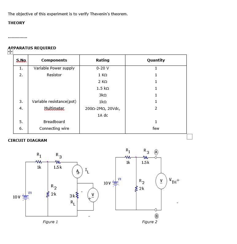
The objective of this experiment is to verify Thevenin's theorem. THEORY APPARATUS REQUIRED S.No 1. 2. 3. 4. 5. 6. 10 V Components Variable


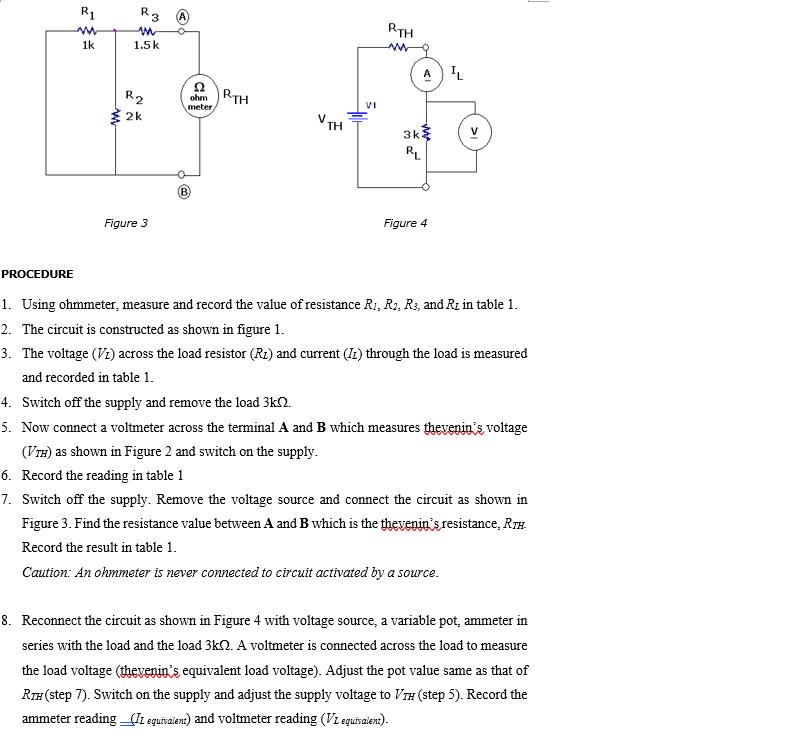
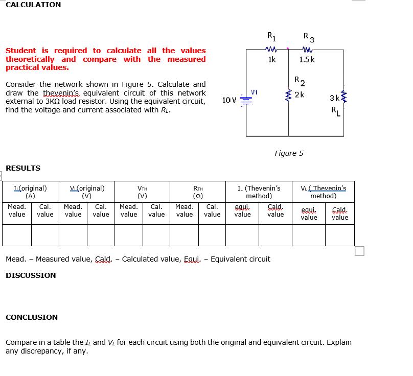
The objective of this experiment is to verify Thevenin's theorem. THEORY APPARATUS REQUIRED S.No 1. 2. 3. 4. 5. 6. 10 V Components Variable Power supply Resistor VI Variable resistance(pot) Multimeter CIRCUIT DIAGRAM Breadboard Connecting wire R 1k www R3 1.5 k R2 2k Figure 1 3k AL RL Rating 0-20 V 1 2 1.5 3kn 1kQ 2002-2M2, 20Vdc, 1A dc 10 V VI R www 1k Quantity 1 1 1 1 1 1 R3 M 1.5k R 2k 2 1 few @ Figure 2 VVTH+ PROCEDURE R1 m 1k ww R3 m 1.5k R 2k Figure 3 3 ohm RTH meter, VTH VI RTH www 3k RL AIL Figure 4 1. Using ohmmeter, measure and record the value of resistance R1, R2, R3, and Ri in table 1. 2. The circuit is constructed as shown in figure 1. 3. The voltage (VI) across the load resistor (R) and current (II) through the load is measured and recorded in table 1. 4. Switch off the supply and remove the load 3k. 5. Now connect a voltmeter across the terminal A and B which measures thevenin's voltage (VTH) as shown in Figure 2 and switch on the supply. 6. Record the reading in table 1 7. Switch off the supply. Remove the voltage source and connect the circuit as shown in Figure 3. Find the resistance value between A and B which is the thevenin's resistance, RTH Record the result in table 1. Caution: An ohmmeter is never connected to circuit activated by a source. 8. Reconnect the circuit as shown in Figure 4 with voltage source, a variable pot, ammeter in series with the load and the load 3k. A voltmeter is connected across the load to measure the load voltage (thevenin's equivalent load voltage). Adjust the pot value same as that of RTH (step 7). Switch on the supply and adjust the supply voltage to VH (step 5). Record the ammeter reading _(II equivalent) and voltmeter reading (VI equivalent). CALCULATION Student is required to calculate all the values theoretically and compare with the measured practical values. Consider the network shown in Figure 5. Calculate and draw the thevenin's equivalent circuit of this network external to 3K load resistor. Using the equivalent circuit, find the voltage and current associated with RL. RESULTS L(original) (A) Vi (original) (V) VTH (V) CONCLUSION RTH (22) 10 V VI Mead. Cal. Mead. Cal. Mead. Cal. Mead. Cal. value value value value value value value value value equi. R www 1k IL (Thevenin's method) Mead. - Measured value, Cald. - Calculated value, Equi. - Equivalent circuit DISCUSSION Cald. value KN R3 M 1.5 k R Figure 5 2k www 3k RL VL(Thevenin's method) equi. Cald. value value Compare in a table the IL and VL for each circuit using both the original and equivalent circuit. Explain any discrepancy, if any.
Step by Step Solution
★★★★★
3.32 Rating (158 Votes )
There are 3 Steps involved in it
Step: 1
Your question seems to be about an experiment that is aimed at verifying Thevenins theorem The experiment includes a circuit setup as shown in the ima...
Get Instant Access to Expert-Tailored Solutions
See step-by-step solutions with expert insights and AI powered tools for academic success
Step: 2

Step: 3

Ace Your Homework with AI
Get the answers you need in no time with our AI-driven, step-by-step assistance
Get Started


