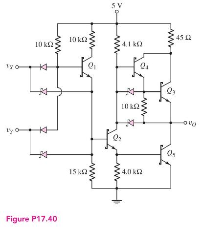
A low-power Schottky TTL logic circuit is shown in Figure P17.40. Assume a transistor current gain of
Question:
A low-power Schottky TTL logic circuit is shown in Figure P17.40. Assume a transistor current gain of \(\beta=30\) for all transistors.
(a) Calculate the maximum fanout for \(v_{X}=v_{Y}=3.6 \mathrm{~V}\).
(b) Using the results of part (a), determine the power dissipated in the circuit for \(v_{X}=v_{Y}=3.6 \mathrm{~V}\).

Fantastic news! We've Found the answer you've been seeking!
Step by Step Answer:
Related Book For 

Microelectronics Circuit Analysis And Design
ISBN: 9780071289474
4th Edition
Authors: Donald A. Neamen
Question Posted:


