

Question: Figure 20.26 shows the flowsheet for a process for the production of G from A. The feed stream of A (entering through valve V-1) is
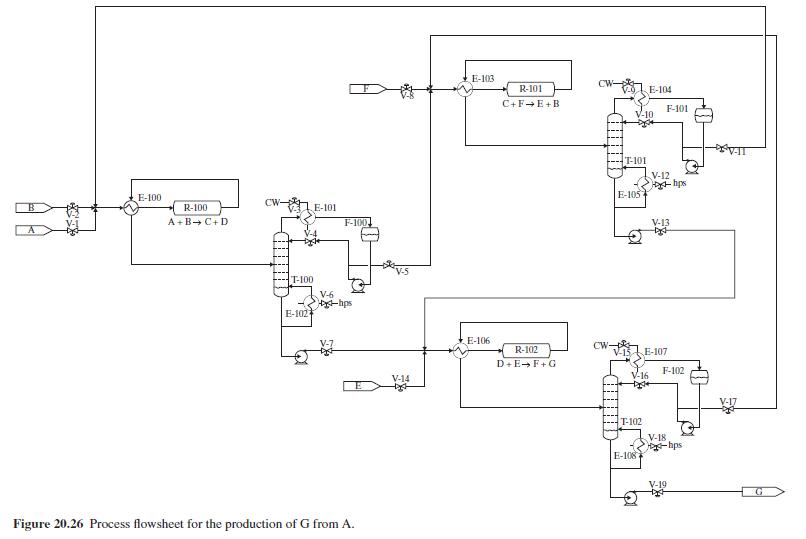
Figure 20.26 shows the flowsheet for a process for the production of G from A. The feed stream of A (entering through valve V-1) is mixed with a makeup stream of \(B\) (entering through valve \(\mathrm{V}\)-2) and a recycle stream composed mostly of \(\mathrm{B}\), and the resulting stream is heated in E-100 and then fed to adiabatic PFR, R-100 in which occurs the exothermic reaction: A + B \(\rightarrow \mathrm{C}+\mathrm{D}\). The \(\mathrm{R}-100\) effluent is separated in column T-100 into a bottoms stream rich in D, and a distillate rich in C. The distillate is mixed with a makeup stream of \(\mathrm{F}\) (entering through valve V-8) and an F-rich recycle stream, and the resulting stream is heated in E-103 and then fed to adiabatic PFR, R-101 in which occurs the exothermic reaction: \(\mathrm{C}+\mathrm{F} \rightarrow \mathrm{E}+\mathrm{B}\). The \(\mathrm{R}-101\) effluent is separated in column T-101 into a bottoms stream rich in \(\mathrm{E}\) and a distillate rich in B, which is recycled. The bottoms from T-101 (rich in E) is mixed with the bottoms from T-100 (rich in D) and a makeup stream of E (entering through valve V-14), and the resulting stream is heated in E-106 and then fed to adiabatic PFR, R-102 in which occurs the exothermic reaction: \(\mathrm{D}+\mathrm{E} \rightarrow \mathrm{F}+\mathrm{G}\). The \(\mathrm{R}-102\) effluent is separated in column T-102 into a bottoms stream rich in \(\mathrm{G}\) and a distillate rich in \(F\), which is recycled. The relative volatilities of the participating components are in the order: \(\alpha_{A}>\alpha_{B}>\alpha_{C}>\alpha_{D}>\alpha_{E}>\alpha_{F}>\alpha_{G}\).
You are requested to suggest a plantwide control system to enable stable operation of the process providing G on demand. Your solution should follow the procedure of Luyben et al. and should include the positioning of all control loops in the PFD of Figure 20.26. You are allowed to add control valves to those already in place in the PFD, but only if these are absolutely necessary to meet the requirements.
Figure 20.26:-
E-100 R-100 A+B+C+D CW- E-101 F-100 T-100 V-6 -hps E-102 Figure 20.26 Process flowsheet for the production of G from A. V-14 E-103 CW- R-101 E-104 C+FE+B F-101 -10 E-106 R-102 D+E+F+G T-101 V-12 hps E-105 V-13 CW- E-107 F-102 -16 T-102 V-18 -hps E-108 V-19 V-17
Step by Step Solution
3.34 Rating (166 Votes )
There are 3 Steps involved in it

Get step-by-step solutions from verified subject matter experts