

Question: The state diagram in Figure P2.51 describes a system with states A, B, and C. The system is initialized in State A. The state transition
The state diagram in Figure P2.51 describes a system with states A, B, and C. The system is initialized in State A. The state transition notation x/yz indicates that an input x causes a transition in the direction shown and the system outputs the value yz. For example, an input 1 in State A causes a transition to State B, and the system outputs 01.
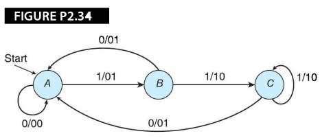
(a) How many flip-flops would be required to construct this system?
(b) If the system receives the input 00010011001010111110010, what would the output be?
FIGURE P2.34 Start 0/00 A 0/01 1/01 B 0/01 1/10 1/10
Step by Step Solution
3.47 Rating (163 Votes )
There are 3 Steps involved in it
a This system has three states and requires two flipflops which can store up to four ... View full answer

Get step-by-step solutions from verified subject matter experts