New Semester
Started
Get
50% OFF
Study Help!
--h --m --s
Claim Now
Question Answers
Textbooks
Find textbooks, questions and answers
Oops, something went wrong!
Change your search query and then try again
S
Books
FREE
Study Help
Expert Questions
Accounting
General Management
Mathematics
Finance
Organizational Behaviour
Law
Physics
Operating System
Management Leadership
Sociology
Programming
Marketing
Database
Computer Network
Economics
Textbooks Solutions
Accounting
Managerial Accounting
Management Leadership
Cost Accounting
Statistics
Business Law
Corporate Finance
Finance
Economics
Auditing
Tutors
Online Tutors
Find a Tutor
Hire a Tutor
Become a Tutor
AI Tutor
AI Study Planner
NEW
Sell Books
Search
Search
Sign In
Register
study help
sciences
structural analysis
Structural Analysis 8th Edition Russell C. Hibbeler - Solutions
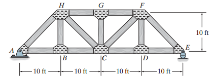
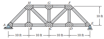
Draw the influence line for the force in member CF, and then determine the maximum force (tension or compression) that can be developed in this member due to a uniform live load of 800 lb/ft which is transmitted to the truss along the bottom cord. Н 10 ft IC ID 10 ft 10 ft -10 ft -10 ft-
Draw the influence line for the force in member CD, and then determine the maximum force (tension or compression) that can be developed in this member due to a uniform live load of 800 lb/ft which acts along the bottom cord of the truss. Н 10 ft IC 10 ft 10 ft- -10 ft- 10 ft
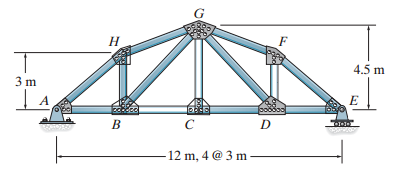
Draw the influence line for the force in member GD, then determine the maximum force (tension or compression) that can be developed in this member due to a uniform live load of 3 kN/m that acts on the bridge deck along the bottom cord of the truss. Н 4.5 m pobdoo B 12 m, 4 @ 3 m
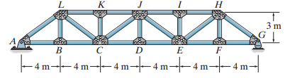
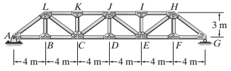
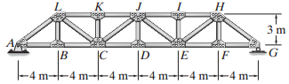
Draw the influence line for the force in member KJ. Н -4m-4m--4 m---4mt-4m--4 m-
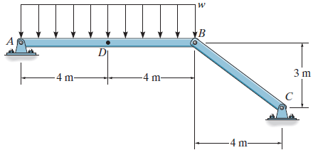
Draw the influence line for the force in member CD. Н Н 3 m Fam--4 m-4 m-4m-4 m--4 m-
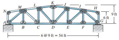
Draw the influence line for the force in member CD. Н T 9ft 6 ft C D E 6 @ 9 ft = 54 ft F
Draw the influence line for the force in member DL. к м Н 6 ft C D E -6 @ 9 ft = 54 ft F B
Draw the influence line for the force in member CL. к Н 6 ft C D E 6 @ 9 ft = 54 ft - B F
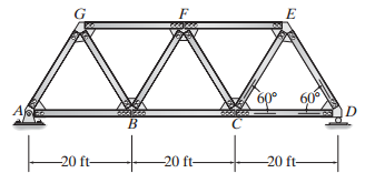
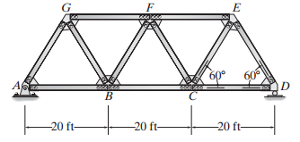
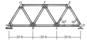
Draw the influence line for the force in member FE of the Warren truss. Indicate numerical values for the peaks. All members have the same length. 60 60° -20 ft- -20 ft- -20 ft-
Draw the influence line for the force in member BF of the Warren truss. Indicate numerical values for the peaks. All members have the same length. -20 ft- -20 ft- -20 ft-
Draw the influence line for the force in member BC of the Warren truss. Indicate numerical values for the peaks. All members have the same length. 60° 60° E200t201- -20 ft- -20 ft- -20 ft-
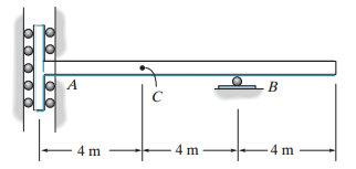
Draw the influence line for (a) The moment at B, (b) The shear at C, and (c) The vertical reaction at B. Solve Prob. 6€“7 using the Muller-Breslau principle. 4 m 4 m 4 m Σ 2υμΟ.
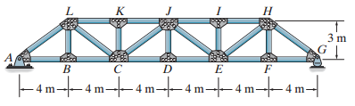
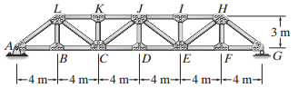
Draw the influence line for the force in member AL. K Н 3 m A IC |F -4 m--4 m--4 m--4 m--4 m-l-4 m- |B
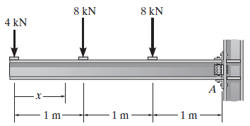
Determine the shear and moment throughout the beam as a function of x. 8 kN 8 kN 4 kN 1 m- 1 m boo
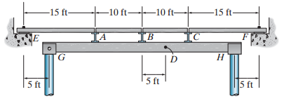
A uniform live load of 250 lb/ft and a single concentrated live force of 1.5 k are to be placed on the floor beams. Determine (a) The maximum positive shear in panel AB, and (b) The maximum moment at D. Assume only vertical reaction occur at the supports. -10 ft -15 ft- -10 ft- -15 ft- Н
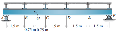
The beam is used to support a dead load of 500 lb/ft, a live load of 2 k/ft, and a concentrated live load of 8 k. Determine (a) The maximum positive (upward) reaction at A, (b) The maximum positive moment at E, and (c) The maximum positive shear just to the right of the support at C.
The beam is used to support a dead load of 400 lb/ft, a live load of 2 k/ft, and a concentrated live load of 8 k. Determine (a) The maximum positive vertical reaction at A, (b) The maximum positive shear just to the right of the support at A, and (c) The maximum negative moment at C.
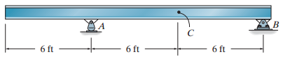
The beam is used to support a dead load of 0.6 k/ft, a live load of 2 k/ft and a concentrated live load of 8 k. Determine (a) The maximum positive (upward) reaction at A, (b) The maximum positive moment at C, and (c) The maximum positive shear just to the right of the support
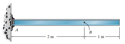
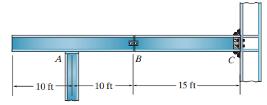
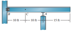
The beam supports a uniform dead load of 0.4 k/ft, a live load of 1.5 k/ft, and a single live concentrated force of 8 k. Determine (a) The maximum positive moment at C, and (b) The maximum positive vertical reaction at B. Assume A is a roller and Bis a pin. IA - 15 ft - в - 1 1 10 ft
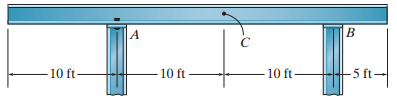
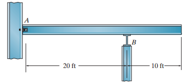
A uniform live load of 300 lb/ft and a single live concentrated force of 1500 lb are to be placed on the beam. The beam has a weight of 150 lb/ft. Determine (a) The maximum vertical reaction at support B, and (b) The maximum negative moment at point B. Assume the support at A is a pin and
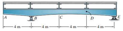
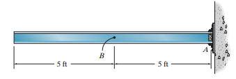
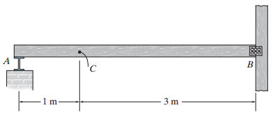
The beam supports a uniform dead load of 500 N/m and a single live concentrated force of 3000 N. Determine (a) The maximum positive moment at C, and (b) The maximum positive shear at C. Assume the support at A is a roller and B is a pin. A. 3 m m
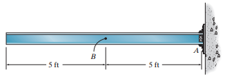
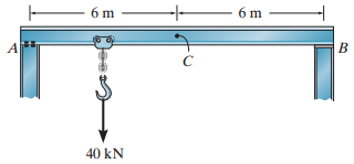
The beam is subjected to a uniform dead load of 1.2 kN/m and a single live load of 40 kN. Determine (a) The maximum moment created by these loads at C, and (b) The maximum positive shear at C. Assume A is a pin. and Bis a roller. 6 m 6 m 40 kN
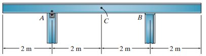
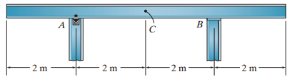
Draw the influence lines for (a) The vertical reaction at A, (b) The vertical reaction at B, (c) The shear just to the right of the support at A, and (d) The moment at C. Assume the support at A is a pin and B is a roller. Solve Prob. 6€“13 using the
Draw the influence lines for (a) The vertical reaction at A, (b) The vertical reaction at B, (c) The shear just to the right of the support at A, and (d) The moment at C. Assume the support at A is a pin and Bis a roller. Solve this problem using the basic method of Sec.
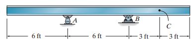
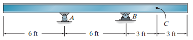
Draw the influence lines for (a) The vertical reaction at A, (b) The shear at C, and (c) The moment at C. Solve Prob. 6€“11 using Muller-Breslau€™s principle. 6 ft 6 ft 3 ft- 3 ft-
Draw the influence line for the force in member JI. K Н Пвосер 3 m в |D -4 m--4 m--4 m--4 m--4 m--4 m- -в-19
Draw the influence line for the force in (a) Member EH and (b) Member JE. L. к Н 3 m IC |D -4 m--4 m--4 m- |F E4 m--4 m--4 m- т
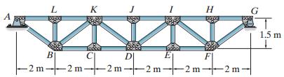
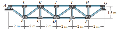
Draw the influence line for the force in member DK. L K A 1.5 m B E F -2 m-2 m- -2 m-2 m- -2 m-2 m-
Draw the influence line for the force in member JK. Н K 1.5 m D| -2 m--2 m- – 2 m -2 m- -2 m 2 m
Draw the influence line for the force in member CD. Н K 1.5 m DI B -2 m-2 m- 2 m -2 m - - 2 m – -2 m- m
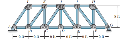
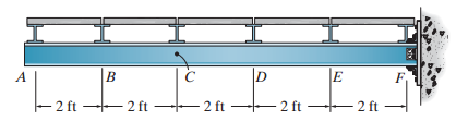
Draw the influence line for the force in member JE. K Н 8 ft A, font's |C G] |B – 8 ft8 ft --8 t - - 8 ft-
Draw the influence line for the force in member KJ.
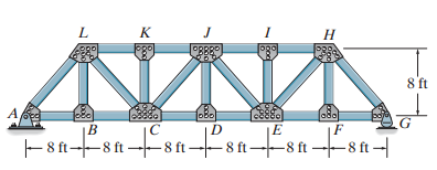
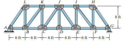
Draw the influence line for the force in (a) Member JI, (b) Member IE, and (c) Member EF. K Н 550. 8 ft l0ва 880 lo0880 A 8800 fonfonfonFonT F 6 ft--6 ft -+ 6 ft- 6 ft-+6 ft -6 ft -
Draw the influence line for the force in (a) Member KJ and (b) Member CJ. Н 8 ft lo0880 JoBo Pon- Fonfont F 6 ft--6 ft – 6 ft- - 6 ft--6 ft
A uniform live load of 1.75 kN/m and a single concentrated live force of 8 kN are placed on the floor beams. If the beams also support a uniform dead load of 250 N/m, determine (a) The maximum negative shear in panel BC of the girder and (b) The maximum positive moment at B. -1.5 m-→
A uniform live load of 6.5 kN/m and a single concentrated live force of 15 kN are placed on the floor beams. If the beams also support a uniform dead load of 600 N/m, determine (a) The maximum positive shear in panel CD of the girder and (b) The maximum positive moment in the girder at D.
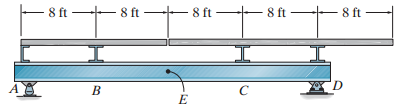
Draw the influence line for the shear in panel CD of the girder. Determine the maximum negative live shear in panel CD due to a uniform live load of 500 lb/ft acting on the top beams. 8 ft 8 ft - 8 ft 8 ft - 8 ft ft B
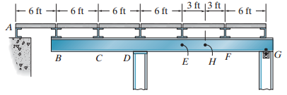
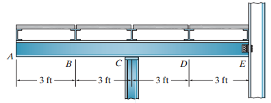
A uniform live load of 0.2 k/ft and a single concentrated live force of 4 k are placed on the floor beams. Determine (a) The maximum positive shear in panel DE of the girder, and (b) The maximum positive moment at H. 3 ft 13 ft + 6ft -6 t- 6 ft 6 ft 6 ft 6 ft A. G F Н
A uniform live load of 4 k/ft and a single concentrated live force of 20 k are placed on the floor beams. If the beams also support a uniform dead load of 700 lb/ft, determine (a) The maximum negative shear in panel DE of the girder and (b) The maximum negative moment in the girder at C.
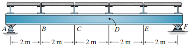
Draw the influence line for the moment at Fin the girder. Determine the maximum positive live moment in the girder at F if a single concentrated live force of 8 kN moves across the top floor beams. Assume the supports for all members can only exert either upward or downward forces on the members. -
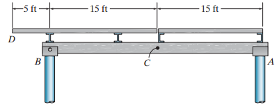
A uniform live load of 0.6 k/ft and a single concentrated live force of 5 k are to be placed on the top beams. Determine (a) The maximum positive shear in panel BC of the girder, and (b) The maximum positive moment at C. Assume the support at Bis a roller and at D a pin. -5 ft - 15 ft 15
Draw the influence line for (a) The shear in panel BC of the girder, and (b) The moment at D. 'F 21 2 m - 2m - 2 m - 2 m 2 m
A uniform live load of 2 k/ft and a single concentrated live force of 6 k are placed on the floor beams. If the beams also support a uniform dead load of 350 lb/ft, determine (a) The maximum positive shear in panel CD of the girder and (b) The maximum negative moment in the girder at D.
A uniform live load of 2.8 kN/m and a single concentrated live force of 20 kN are placed on the floor beams. If the beams also support a uniform dead load of 700 N/m, determine (a) The maximum positive shear in panel BC of the girder and (b) The maximum positive moment in the girder at G.
A uniform live load of 1.8 kN/m and a single concentrated live force of 4 kN are placed on the floor beams. Determine (a) The maximum positive shear in panel BC of the girder and (b) The maximum moment in the girder at G.
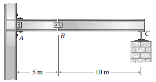
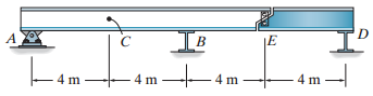
The compound beam is subjected to a uniform dead load of 1.5 kN/m and a single live load of 10 kN. Determine (a) The maximum negative moment created by these loads at A, and (b) The maximum positive shear at B. Assume A is a fixed support,B is a pin, and C is a roller. 10 m
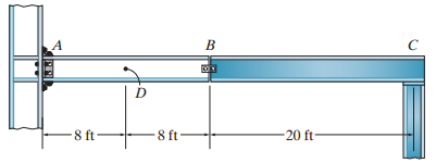
Where should a single 500-lb live load be placed on the beam so it causes the largest moment at D? What is this moment? Assume the support at A is fixed,Bis pinned, and C is a roller. 8 ft- 20 ft- 8 ft
Where should the beam ABC be loaded with a 300 lb/ft uniform distributed live load so it causes (a) The largest moment at point A and (b) The largest shear at D? Calculate the values of the moment and shear. Assume the support at A is fixed,Bis pinned and C is a roller. A 8 ft- 20 ft- 8 ft
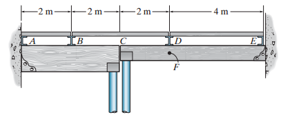
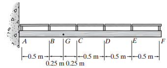
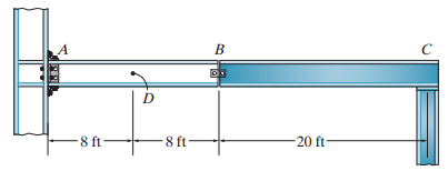
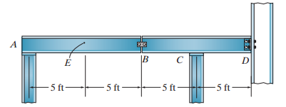
The beam is used to support a dead load of 800 N/m, a live load of 4 kN/m, and a concentrated live load of 20 kN. Determine (a) The maximum positive (upward) reaction at B, (b) The maximum positive moment at C, and (c) The maximum negative shear at C. Assume Band Dare pins. IB 4 m
Draw the influence lines for (a) The vertical reaction at A, (b) The shear at C, and (c) The moment at C. Solve this problem using the basic method of Sec. 6€“1. B -3 ft-3 ft 6 ft 6 ft
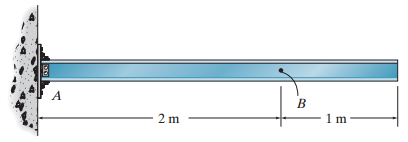
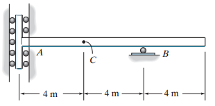
Draw the influence line for (a) The vertical reaction at A, (b) The shear at B, and (c) The moment at B. Assume A is fixed. Solve Prob. 6€“9 using the Muller-Breslau principle. A B 2 m
Draw the influence line for (a) The vertical reaction at A, (b) The shear at B, and (c) The moment at B. Assume A is fixed. Solve this problem using the basic method of Sec. 6€“1. A. 2 m
Draw the influence lines for (a) The vertical reaction at A, (b) The moment at A, and (c) The shear at B. Assume the support at A is fixed. Solve this problem using the basic method of Sec. 6€“1. 5ft 5 ft
Draw the influence lines for (a) The vertical reaction at A, (b) The moment at A, and (c) The shear at B. Assume the support at A is fixed. Solve Prob. 6€“3 using the Muller-Breslau principle. 5 ft 5 ft
Draw the influence lines for (a) The vertical reaction at B, (b) The shear just to the right of the rocker at A, and (c) The moment at C. Solve this problem using the basic method of Sec. 6€“1. 6 ft 6 ft 6 ft
Draw the influence lines for (a) The vertical reaction at B, (b) The shear just to the right of the rocker at A, and (c) The moment at C. Solve Prob. 6€“5 using Muller-Breslau€™s principle. 6 ft 6 ft 6 ft
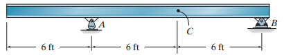
Draw the influence line for (a) The moment at B, (b) The shear at C, and (c) The vertical reaction at B. Solve this problem using the basic method of Sec. 6€“1.The support at A resists only a horizontal force and a bending moment. 4 m 4 m 4 m
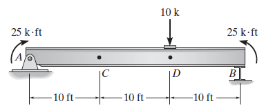
Determine the internal normal force, shear force, and bending moment in the beam at points C and D. Assume the support at B is a roller. Point D is located just to the right of the 10-k load. 10 k 25 k ft 25 k-ft |C D B 10 ft- 10 ft- -10 ft
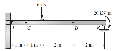
Determine the internal normal force, shear force, and bending moment in the beam at points C and D. Assume the support at A is a pin and B is a roller. 6 kN 20 kN m B_I! |-1 m-|--1 m-- 2 m 2 m-
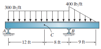
Determine the internal normal force, shear force, and bending moment at points D and E. Assume the reactions at the supports A and B are vertical. 400 lb/ft 300 lb/ft AI IB -12 ft- 8 ft-
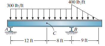
Determine the internal normal force, shear force, and bending moment at point C. Assume the reactions at the supports A and B are vertical. 400 lb/ft 300 lb/ft IB AI -8 ft- -9 ft- 12 ft –
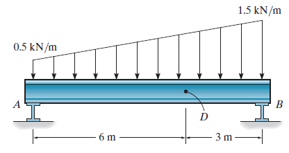
Determine the internal normal force, shear force, and bending moment at point D. Assume the reactions at the supports A and B are vertical. 1.5 kN/m 0.5 kN/m B 3 m -
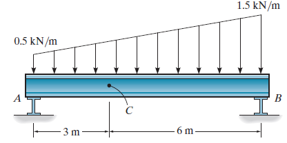
Determine the internal normal force, shear force, and bending moment at point C. Assume the reactions at the supports A and B are vertical. 1.5 kN/m 0.5 kN/m B 6 m - 3 m –
Determine the internal normal force, shear force, and bending moment at point D.Take w = 150 N/m. 3 m -4 m- - 4 m– -4 m-
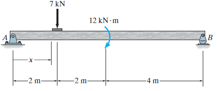
Determine the shear and moment throughout the beam as a function of x. 7 kN 12 kN m B -4 m- -2 m- -2 m-
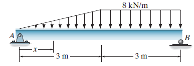
Determine the shear and moment throughout the beam as a function of x. 8 kN/m 3 m
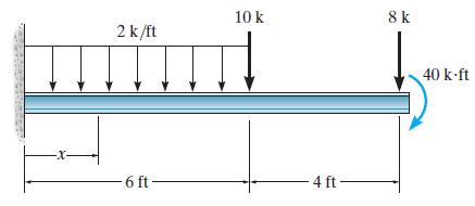
Determine the shear and moment throughout the beam as functions of x. 8 k 10 k 2 k/ft 40 k-ft - 6 ft 4 ft -
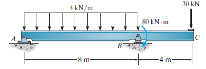
Draw the moment diagrams for the beam using the method of superposition. Consider the beam to be cantilevered from the pin support at A. 30 kN 4 kN/m 80 kN- m 4 m- 8 m-
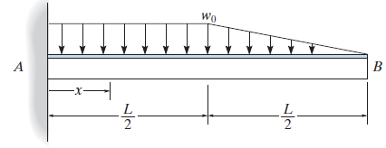
Determine the shear and moment in the beam as functions of x. Wo B /27
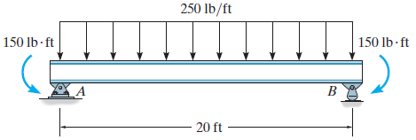
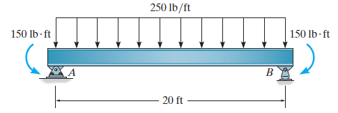
Draw the moment diagrams for the beam using the method of superposition. Consider the beam to be simply supported at A and B as shown. 250 lb/ft 150 lb - ft 150 lb- ft B - 20 ft
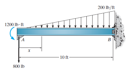
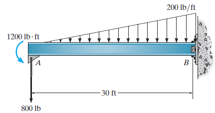
Determine the shear and moment in the beam as a function of x. 200 lb/ft 1200 lb - ft х 10 ft - 800 lb
Draw the moment diagrams for the beam using the method of superposition. Consider the beam to be cantilevered from end A. 250 lb/ft 150 lb - ft 150 lb ft B 20 ft
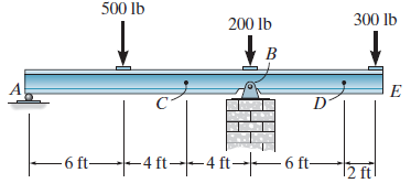
Draw the shear and moment diagrams for the beam. 500 lb 300 lb 200 lb E -4 ft--4 ft→–6 ft- -6 ft- 2 ft
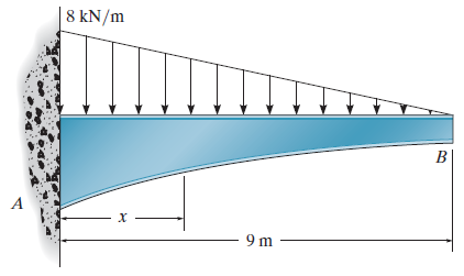
Determine the shear and moment throughout the tapered beam as a function of x. | 8 kN/m B х - 9 m
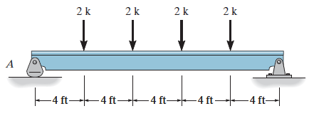
Draw the shear and moment diagrams for the beam. 2 k 2k 2 k 2 k -4 ft 4 ft- 4 ft -4 ft -4 ft-
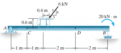
Draw the shear and moment diagrams for the beam. 6 kN 0.4 m 20 kN - m 0.6 m B |C D 380 m--1 m- -2 m -2 m-
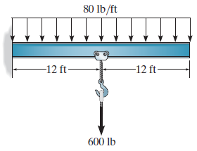
Draw the moment diagrams for the beam using the method of superposition. 80 lb/ft -12 ft- -12 ft- 600 lb
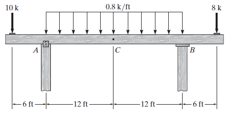
Draw the shear and moment diagrams for the beam. 0.8 k/ft 8 k 10 k |C ton- - 6 ft- -12 ft- -12 ft– 6 ft→
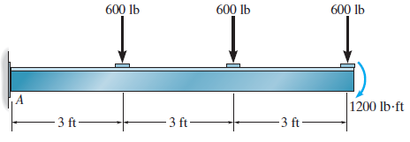
Draw the moment diagrams for the beam using the method of superposition.The beam is cantilevered from A. 600 lb 600 lb 600 lb |1200 lb-ft 3 ft- - 3 ft- - 3 ft-
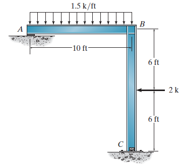
Draw the shear and moment diagrams for each member of the frame. Assume the frame is roller supported at A and pin supported at C. 1.5 k/ft B -10 ft- 6 ft 2 k 6 ft
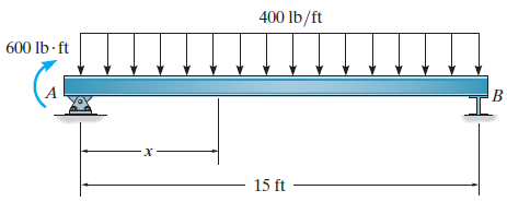
Draw the shear and moment diagrams for the beam. 400 lb/ft 600 lb ft B х 15 ft
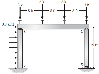
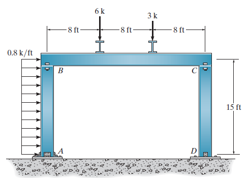
Draw the shear and moment diagrams for each member of the frame. Assume the frame is pin connected at B, C, and D and A is fixed. 6 k 6 k 3 k 3 k 8 ft - 8 ft 8 ft 0.8 k/ft 15 ft
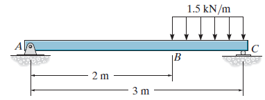
Draw the shear and moment diagrams for the beam. 1.5 kN/m ДП. |B 2 m 3 m
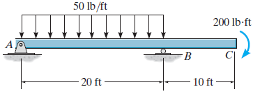
Draw the shear and bending-moment diagrams for the beam. 50 lb/ft 200 lb-ft - 20 ft 10 ft –
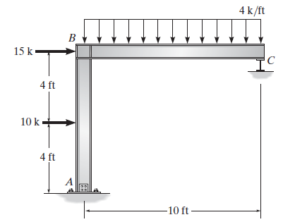
Draw the shear and moment diagrams for each member of the frame. Assume the frame is pin connected at A, and C is a roller. 4 k/ft Ви 15 k тс 4 ft 10 k 4 ft -10 ft
Draw the shear and moment diagrams for each of the three members of the frame. Assume the frame is pin connected at B, C, and D and A is fixed. 6 k 3k 8 ft -8 ft- 8 ft 0.8 k/ft B 15 ft
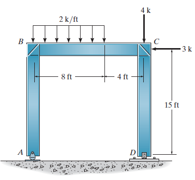
Draw the shear and moment diagrams for each member of the frame. Assume A is a rocker, and D is pinned. 4 k 2 k/ft B . 3k – 8 ft 4 ft 15 ft DLA.
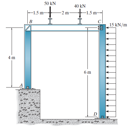
Draw the shear and moment diagrams for each of the three members of the frame. Assume the frame is pin connected at A, C, and D and there is a fixed joint at B. 50 kN 40 kN -1.5 m- -2 m- -1.5 m- |в c| 15 kN/m 4 m 6 m A
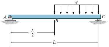
Draw the shear and moment diagrams for the beam. |C |B L-
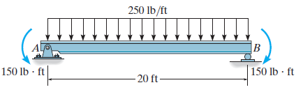
Draw the shear and moment diagrams for the beam. 250 lb/ft B 150 lb · ft 150 lb · ft 20 ft-
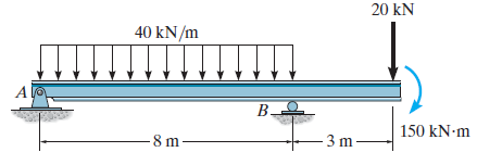
Draw the shear and moment diagrams for the beam. 20 kN 40 kN/m A 150 kN-m -8 m
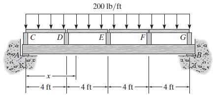
Draw the shear and moment diagrams for the beam. 200 lb/ft B: -4 ft- -4 ft- - 4 ft – -4 ft
Draw the shear and moment diagrams for the beam. 200 lb/ft 1200 lb- ft – 30 ft - 800 lb
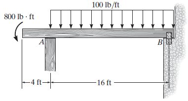
Draw the shear and moment diagrams of the beam. Assume the support at B is a pin and A is a roller. 100 lb/ft 800 lb - ft B В Ш -16 ft -
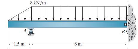
Draw the shear and moment diagrams for the beam. Assume the support at B is a pin. 8 kN/m 6 m -1.5 m -
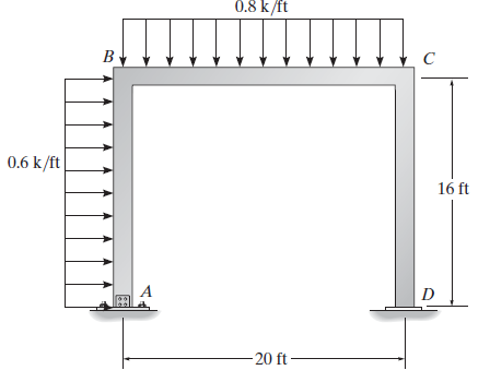
Draw the shear and moment diagrams for each member of the frame. Assume the support at A is a pin and D is a roller. 0.8 k/ft B 0.6 k/ft 16 ft -20 ft -
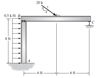
Draw the shear and moment diagrams for each member of the frame. Assume A is fixed, the joint at B is a pin, and support C is a roller. 20 k 0.5 k/ft B 8 ft |A - 6 ft- 6 ft –
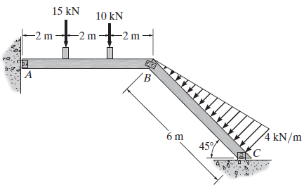
Draw the shear and moment diagrams for each member of the frame.The members are pin connected at A, B, and C. 15 kN 10 kN -2 m -2 m -2 m A 4 kN/m 6 m 45%
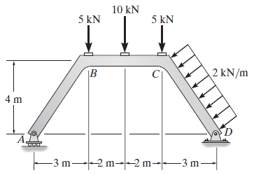
Draw the shear and moment diagrams for each member of the frame. 10 kN 5 kN 5 kN IB 2 kN/m 4 m F3m -3 m--2 m--2 m-–3 m-
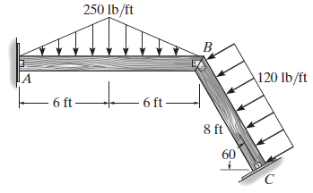
Draw the shear and moment diagrams for each member of the frame. The joints at A, B, and C are pin connected. 250 lb/ft B 120 lb/ft JA 6 ft- 6 ft – 8 ft 60
Showing 1200 - 1300
of 1426
1
2
3
4
5
6
7
8
9
10
11
12
13
14
15
Step by Step Answers


![K Н 8 ft A, font's |C G] |B – 8 ft8 ft --8 t - - 8 ft-](https://dsd5zvtm8ll6.cloudfront.net/si.question.images/images/question_images/1530/9/5/9/4515b40965ba819d1530941619556.jpg)