All Matches
Solution Library
Expert Answer
Textbooks
Search Textbook questions, tutors and Books
Oops, something went wrong!
Change your search query and then try again
Toggle navigation
FREE Trial
S
Books
FREE
Tutors
Study Help
Expert Questions
Accounting
General Management
Mathematics
Finance
Organizational Behaviour
Law
Physics
Operating System
Management Leadership
Sociology
Programming
Marketing
Database
Computer Network
Economics
Textbooks Solutions
Accounting
Managerial Accounting
Management Leadership
Cost Accounting
Statistics
Business Law
Corporate Finance
Finance
Economics
Auditing
Hire a Tutor
AI Study Help
New
Search
Search
Sign In
Register
study help
engineering
mechanical vibration analysis
Questions and Answers of
Mechanical Vibration Analysis
What difficulties arise if a system parameter such as \(k\) or \(m\) is known only approximately?
If the structure responds in a way that is unacceptable for a particular application, what options exist for the designer?
If the analyst decides that a structure requires control in order to fulfill the needs of an application, describe the procedure by which a control force can be derived and then verified that it
A simple system is represented by the governing equation\[ m \ddot{x}+k x=F(t) \]where \(m=1 \mathrm{~kg}, k=10 \mathrm{~N} / \mathrm{m}\), and \(F(t)=\cos t\) \(\mathrm{N}\), with zero initial
Consider the simple system, \(m \ddot{x}+k x=F(t)\), where \(F(t)\) is known and \(m\) and \(k\) are unknown. Suppose the initial conditions are both equal to zero. What can we determine about the
Consider the simple system, \(m \ddot{x}+k x=F(t)\), where \(F(t)\) and steady-state solution \(x_{s}(t)\) are known and \(m\) and \(k\) are unknown. Suppose the initial conditions are both equal to
Consider the simple system, \(m \ddot{x}+k x=F(t)\), where steady-state solution \(x_{s}(t), m\), and \(k\) are known and \(F(t)\) is unknown. Suppose the initial conditions are both equal to zero.
Consider a damped oscillator where the force is a function of velocity,\[ m \ddot{x}+c \dot{x}+k x=F_{0} \dot{x} \]Discuss the stability of this system in terms of the parameters \(m,c, k, F_{0}\).
Consider a damped oscillator where the force is a function of displacement,\[ m \ddot{x}+c \dot{x}+k x=F_{0} x \]Discuss the stability of this system in terms of the parameters \(m,c, k, F_{0}\).
For an \(m-c-k\) oscillator subjected to harmonic loading, \(A k \cos \omega t\), conceive a design so that the displacement response \(|x(t)|
For an oscillator governed by \(\ddot{x}+2 \zeta \omega_{n} \dot{x}+\omega_{n}^{2} x=\) \(\cos \omega t\), conceive a design so that the displacement response \(|x(t)|
Solve Problem 37 for the load shown in Figure 4.36. A F(t) 0 Figure 4.36: Ramp loading.
Solve Problem 37 for the load as shown in Figure 4.37. A F(t) 0 Figure 4.37: Simplified representation of a shock loading.
Consider the system shown in Figure 5.21. Let \(x_{1}\) and \(\theta\) be the displacement and angle of rotation of the pulley measured from their original locations when the spring is undeformed.
Consider the point mass supported by two linear springs shown in Figure 5.22. The springs are undeformed when the mass and the springs are along a straight line, where the coordinate \(y\) defines
Consider again the system shown in Figure 2.58, reproduced in Figure 5.23. The system consists of massless pulleys, a block of mass \(m\), and two linear springs. The coordinate, \(\theta\), is the
Consider the system shown in Figure 5.24. Let \(x\) be the displacement of the mass measured from its original location where the springs are undeformed. Assume that the pulleys are massless and the
Consider again the system shown in Figure 2.46, reproduced in Figure 5.25. The bar is horizontal when the massless springs are undeformed. Assume that the rod mass is \(m\), and the mass moment of
Consider again the system shown in Figure 2.56, reproduced in Figure 5.26. A disk is on an inclined plane supported by a spring. The coordinates \(x\) and \(\theta\) are zero when the spring is
Consider the system comprised of the disk, pulley, and block shown in Figure 5.27. The spring is connected to the disk of mass \(M\) at its mass center. The disk has radius \(r\) and mass moment of
Consider the two degree-of-freedom system shown in Figure 5.28. The springs are undeformed when the rods are horizontal. The mass of each rod is \(m\), with length \(L\), and mass moment of inertia
Derive the equation of motion for the system in Figure 5.21 for generalized coordinate \(x_{2}\) using(a) Lagrange's equation, and(b) Hamilton's principle. k M, R. IG. x1 m X2 Figure 5.21:
Derive the equation of motion for the system in Figure 5.22 for generalized coordinate \(y\) using(a) Lagrange's equation, and(b) Hamilton's principle. m ww www Figure 5.22: Point mass supported by
Derive the equation of motion for the system in Figure 5.23 for generalized coordinate \(x_{2}\) using(a) Lagrange's equation, and(b) Hamilton's principle. eeeee ellee m T Figure 5.23: A mass
Derive the equation of motion for the system in Figure 5.24 for generalized coordinate \(x\) using(a) Lagrange's equation, and(b) Hamilton's principle. k -0000 x m ellel k Figure 5.24: A mass
Derive the equation of motion for the system in Figure 5.25 for generalized coordinate \(\theta\) using(a) Lagrange's equation, and(b) Hamilton's principle. K 6000 Figure 5.25: Restrained rigid rod. k
Derive the equation of motion for the system in Figure 5.26 for generalized coordinate \(x\) using(a) Lagrange's equation, and(b) Hamilton's principle. eeeee IG 8 Position of the disk when the spring
Derive the equation of motion for the system in Figure 5.27 for generalized coordinate \(x\) using(a) Lagrange's equation, and(b) Hamilton's principle. k mmm M. r. IG x m Figure 5.27:
Derive the equations of motion for the system in Figure 5.28 for generalized coordinates \(\theta_{1}\) and \(\theta_{2}\) using(a) Lagrange's equation and(b) Hamilton's principle. m. L. IG eeeee m.
Consider again the system of Figure 2.52, reproduced in Figure 5.29. A disk of mass \(m\) and mass moment of inertia \(I_{G}\) is supported by a massless spring and a rope. Derive the equation of
Consider again the system of Figure 2.53, reproduced in Figure 5.30. A mass \(m\) is suspended by a pulley system with a spring. Derive the equation of motion of the system using(a) Lagrange's
Consider again the system of Figure 2.54, reproduced in Figure 5.31. Derive the equation of motion of the system using (a) Lagrange's equation, and (b) Hamilton's principle, for generalized
Consider again the system of Figure 2.57, reproduced in Figure 5.32. Derive the equation of motion using (a) Lagrange's equation, and (b) Hamilton's principle, for generalized coordinate \(x\). eeeee
For the simple pendulum of Figure 5.33, derive the governing equation of motion assuming (a) that \(m\) is a point mass, and (b) that the mass is a sphere with small but finite mass moment of
The lightweight bar in Figure 5.34 is released from rest when the spring is undeformed at \(\theta=0\). The two masses at \(A\) and \(B\) slide in frictionless guides that are horizontal at the left
The spring supporting the rod-sphere system in Figure 5.35 is undeformed when the rod is horizontal. Assume the rod mass is negligible. The roller from which the spring is suspended permits the
Verify Equation 5.20,\[ m_{i} \ddot{\mathbf{r}}_{i} \cdot \frac{\partial \mathbf{r}_{i}}{\partial q_{k}}=\left[\frac{d}{d t}\left(\frac{\partial}{\partial
For Example 5.10, use Newton's second law of motion to derive the equations of motion. Example 5.10 The Generalized Force Consider the simple pendulum suspended from a block that can translate on a
Derive Equation 5.28, assuming a linear model with \(m_{i j}=\) constant and \(k_{i j}=\) constant ,\[ [m]\{\ddot{q}\}+[k]\{q\}=\{0\} \]
Formulate the problem of Example 5.13 where the string is elastic with stiffness \(k\) and can stretch. Derive the equations of motion. Example 5.13 Two Mass System Equations from Lagrange's Equation
For the elastic pendulum discussed in Example 5.14, and shown in Figure 5.19, derive the governing equations of motion using Lagrange's equation. Example 5.14 Hamilton's Principle for the Derivation
In the pendulum shown in Figure 5.36 the length \(r\) is variable. Derive the equations of motion. Discuss the possibility and implications if \(\omega=\dot{\theta}\). x = A sin oot m Figure 5.36:
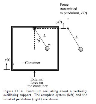
(a) For the elastically supported mass on a vertically moving base shown in Figure 5.37 derive the governing equation of motion first using d'Alembert's principle, and then using Lagrange's equation.
Consider the motion of a pendulum that is supported by springs that are elastically restrained to horizontal motion, as depicted in Figure 5.38. Assume that the springs are massless and remain
For a pendulum supported from a horizontally restrained mass, as shown in Figure 5.39, derive the governing equations of motion using (a) Lagrange's equation and (b) Hamilton's principle. Identify
Fill in the missing steps in the derivation of the equations of motion for Example 5.8, that is, Equations 5.15 and 5.16 . Example 5.8 Double Compound Pendulum Equa- tions from Newton's Second Law
Use Lagrange's equation to derive the equations of motion governing the displacements \(x_{1}\) and \(x_{2}\) for the two degree-of-freedom system depicted in Figure 5.40 . 12 -6000 6000 Figure 5.40:
Use Lagrange's equation to derive the equations governing the rotations \(\theta_{1}, \theta_{2}\), and \(\theta_{3}\) for the springconnected triple pendulum system shown in Figure 5.41. 6000 k 6000
A pendulum is suspended from a torsionally restrained disk, as in Figure 5.42, where \(\alpha\) is the angle of rotation of the disk, and \(\theta\) is the relative angle of the pendulum measured
A rigid beam acts as a compound pendulum, suspended from an elastically restrained block that can undergo horizontal motion, as drawn in Figure 5.43. Derive the equations of motion using Lagrange's
For the inverted simple pendulum of length \(l\) and mass \(m_{2}\), supported on a cart of mass \(m_{1}\), as shown in Figure 5.44, derive the equations of motion if the cart is forced by \(F(t)\).
The system in Figure 5.45 oscillates about the equilibrium position denoted by the horizontal lines. The coil torsional springs are each undeformed when \(\theta_{1}=\theta_{2}=0\). If the link
Figure 5.46 shows a pulley system that is acted on by an applied moment \(M(t)\), resulting in oscillatory motion. Use Lagrange's equation to derive the equations of motion. Identify the generalized
The system sketched in Figure 5.47 depicts two shafts coupled through meshing gears. Assume that gears 2 and 4 have gear ratio \(n=r_{2} / r_{4}\), and that external moment \(M(t)\) is applied to
Solve Equation 3.6, \(\ddot{x}+2 \zeta \omega_{n} \dot{x}+\omega_{n}^{2} x=0\) for \(\zeta>1\).\
Derive Equation 3.9, \(x(t)=C e^{-\zeta \omega_{n} t} \cos \left(\omega_{d} t-\phi\right)\).
(a) The response of an oscillator with mass \(m=1\) kg is shown in Figure 3.51. What can you say about the properties of the oscillator and the response? Determine the equation of motion and the
(a) Derive the equation of motion for a mass-springdamper system in free vibration. Solve for the transient response \(x(t)\) that is driven by the initial conditions \(x(0)=x_{0}\) and
A mass-spring-damper system is tested to determine the value of \(c\). Assume \(k=10 \mathrm{lb} /\) in and \(m=2\) slug. (a) If the vibrational amplitude is observed to decrease to \(33 \%\) of its
A periodic torque with a maximum value of \(1.0 \mathrm{~N}-\mathrm{m}\) at a frequency of \(5.0 \mathrm{rad} / \mathrm{s}\) is applied to a flywheel suspended from a wire. The flywheel has a moment
A periodic force \(F(t)=A \cos \omega t\) is applied to the damped system shown in Figure 3.53. Calculate the work done in one cycle during the steady-state response where \(A=50 \mathrm{~N},
This problem investigates the number of cycles \(n\) re-quired for a structural oscillation amplitude to decay to \(x \%\) of its maximum. (a) What is the expression for the logarithmic decrement in
Solve for \(t_{\max }\) in Equation 3.17 in general for arbitrary variables. Then evaluate \(t_{\max }\) numerically for the cases in Table 3.1. Plot each case and discuss trends. Table 3.1: Cases
Coulomb used the following method to determine the viscosity of liquids. A thin plate of weight \(W\) is suspended vertically and set into motion, first in air and then fully submerged in the
The bell-crank mechanism depicted in Figure 3.55 is rotated slightly and released to oscillate in free vibration. Derive the damped frequency of oscillation \(\omega_{d}\) and the critical damping
An automobile's suspension system determines the vehicle's response to inputs from uneven road surfaces. Figure 3.56 shows a drawing of a suspension system that includes a coil spring, a shock
For the system in Figure 3.57, the forcing per unit mass is \(F(t) / m=10 \sin 15 t \mathrm{ft} / \mathrm{s}^{2}\). Solve for the transient response, the steady-state response, and the constants of
For a mass-spring-damper system under harmonic loading per unit mass \(F(t) / m=\cos \omega t \mathrm{ft} / \mathrm{s}^{2}\), solve for the response amplitude for the case where \(k=\) \(20
Solve Problem 14 for \(k=40 \mathrm{lb} /\) in and \(W=20 \mathrm{lb}\). 14. For a mass-spring-damper system under harmonic loading per unit mass F(t)/mcos ut ft/s, solve wt for the response
Solve Problem 14 for \(k=20 \mathrm{lb} /\) in and \(W=20 \mathrm{lb}\). 14. For a mass-spring-damper system under harmonic loading per unit mass F(t)/mcos ut ft/s, solve wt for the response
For Problem 14 where \(k=20 \mathrm{lb} /\) in and \(W=40 \mathrm{lb}\), solve for the steady-state responses in \(\mathrm{ft} / \mathrm{s}^{2}\) to the following excitation forces per unit mass:(a)
For what range of frequency ratios \(\omega / \omega_{n}\) will the magnification factor \(\beta\) be greater than 1 for the idealized model of Figure 3.58? For what range of frequency ratios will
For the system of Figure 3.58, what do the initial conditions have to be so that both integration constants \(C\) and \(\phi\) equal zero in Equation 3.37? x(t) = Cent cos(wato) + B coswt + B sin wt,
Derive \(C\) and \(\phi\) to verify Equations 3.38 and 3.39 . C = x(0) - B COS (3.38) [(0) + [x(0) B]wn - Bw = tan (3.39) [x(0) - B]wd
For each case in Table 3.2, for the governing equation \(\ddot{x}+2 \zeta \omega_{n} \dot{x}+\omega_{n}^{2} x=A \cos \omega t\), evaluate \(C\) and \(\phi\), and \(B_{1}\) and \(B_{2}\) in Equation
Derive Equations 3.44 and 3.45:\[ \begin{aligned} |G(i \omega)| & =\frac{1}{k \sqrt{\left(1-\left(\omega / \omega_{n}\right)^{2}\right)^{2}+\left(2 \zeta \omega / \omega_{n}\right)^{2}}} \\ \phi &
Derive \(B_{1}\) and \(B_{2}\) in Equations 3.48 and 3.49:\[ \begin{aligned} & -\omega_{b}^{2} B_{1}+2 \zeta \omega_{n} \omega_{b} B_{2}+\omega_{n}^{2} B_{1}=A_{1} \\ & -\omega_{b}^{2}
Plot \(F_{T} / k Y\), Equation 3.52, vs. \(\omega_{b} / \omega_{n}\) for \(\zeta=\) \(0.05,0.10\), and 0.25 . 1/2 kY =()[ 1+ (20wo/wn) - [(1 w/w) + (2(wo/wn) ] (3.52)
The base-excited system of Figure 3.59 is driven by a force with frequencies in the range \(1.0 \leq \omega_{b} / \omega_{n} \leq\) 2.0. For parameter values \(m=1 \mathrm{~kg}, k=9 \mathrm{~N} /
Solve for the response of the base-excited system governed by \(\ddot{x}+2 \zeta \omega_{n} \dot{x}+\omega_{n}^{2} x=2 \zeta \omega_{n} \dot{y}+\omega_{n}^{2} y\), where \(y(t)=A \exp \left(i
The response of a system excited at its base by \(y(t)=Y \sin \omega t\) is given by\[ x(t)=X \sin \left(\omega_{b} t-\phi\right) \]with\[ \frac{X}{Y}=\left[\frac{1+\left(2 \zeta \omega_{b} /
A vibration sensor has a damping ratio \(\zeta=0.55\) and a natural frequency \(f_{n}=10 \mathrm{~Hz}\). Estimate the lowest frequency that can be measured with \(1 \%\) error.
An engine of mass \(200 \mathrm{~kg}\) is to be supported on four helical springs. When the engine speed is \(1000 \mathrm{rpm}\) there is a primary vertical periodic force of maximum value \(350
A rotating machine component has an eccentricity of approximately \(e=0.1 \mathrm{~mm}\) in its center of mass resulting in a harmonic load on the structure. Assume, using the notation of the
Derive the general equations of motion, Equations 3.55 and 3.56 ,\[ \begin{aligned} & m\left(\ddot{x}-\varepsilon \dot{\Omega}^{2} \cos \Omega-\varepsilon \ddot{\Omega} \sin \Omega\right)+k_{x} x=0
A simple model of a seismometer is shown in Figure 3.60. The top view shows how a pen attached to the seismometer mass traces out a pattern on a paper grid that is on a roller. The side view provides
A machine is loaded by a periodic "sawtooth" shaped force, as depicted in Figure 3.61. The load is assumed to have existed for a very long time. Model this force using: (a) a one-term Fourier series,
Solve Problem 33 with (a) \(T=2 \mathrm{~s}\), and (b) \(T=\) \(0.5 \mathrm{~s}\).
Solve Problem 33 with \(A=2 \mathrm{~cm}\).
Solve Problem 33 with \(\zeta=1.0\).
A body is subjected to the two harmonic motions,\[ \begin{aligned} & x_{1}(t)=100 \sin \left(\omega t+\frac{\pi}{3}\right) \mathrm{mm} \\ & x_{2}(t)=50 \sin \left(\omega t+\frac{\pi}{6}\right)
An undamped system is forced by the periodic function shown in Figure 3.62. Derive the Fourier series representation for this function, and solve for the response assuming zero initial conditions. FO
For Example 3.20, plot \(F(t)\) and \(x(t)\) for the case \(\omega_{n}=6 \omega_{T}\). Compare the results with those of Figure 3.50 and discuss. Assume \(T=1 \mathrm{~s}, F_{0}=1 \mathrm{~N}\),
Solve Example 3.20 where the structure has viscous damping, that is, the governing equation of motion is \(\ddot{x}+2 \zeta \omega_{n} \dot{x}+\omega_{n}^{2}=F(t)\), the forcing \(F(t)\) is the same
Solve Example 3.20, as in Problem 40, with \(\omega_{n}=\) \(4 \omega_{T} \mathrm{rad} / \mathrm{s}\). Example 3.20 Response to a Square Wave Using Fourier Series 47 Consider the simple undamped
A base-excited structure is governed by the equation \(\ddot{x}+2 \zeta \omega_{n} \dot{x}+\omega_{n}^{2} x=2 \zeta \omega_{n} \dot{y}+\omega_{n}^{2} y\), where \(y(t)\) is the base motion. Solve for
Solve Problem 42 where the input is given by the square wave of Figure 3.63. y(t) B - B T Figure 3.63: Square wave base motion.
Solve Problem 42 where the input is given by the function \(\sin t, 0 \leq t \leq \pi\), shown in Figure 3.64, repeated periodically. C y(t) 0 Figure 3.64: Base motion driven by sint.
The beam in Figure 2.30 vibrates as a result of loading not shown. State the necessary assumptions to reduce this problem to a one degree-of-freedom oscillator. Then derive the equation of
If a beam is supported continuously on a foundation, as shown in Figure 2.31, damping must be added to an idealized model to represent the viscous effects of the mat foundation. How would you
Showing 300 - 400
of 2655
1
2
3
4
5
6
7
8
9
10
11
12
13
14
15
Last