All Matches
Solution Library
Expert Answer
Textbooks
Search Textbook questions, tutors and Books
Oops, something went wrong!
Change your search query and then try again
Toggle navigation
FREE Trial
S
Books
FREE
Tutors
Study Help
Expert Questions
Accounting
General Management
Mathematics
Finance
Organizational Behaviour
Law
Physics
Operating System
Management Leadership
Sociology
Programming
Marketing
Database
Computer Network
Economics
Textbooks Solutions
Accounting
Managerial Accounting
Management Leadership
Cost Accounting
Statistics
Business Law
Corporate Finance
Finance
Economics
Auditing
Hire a Tutor
AI Study Help
New
Search
Search
Sign In
Register
study help
engineering
chemical engineering
Questions and Answers of
Chemical Engineering
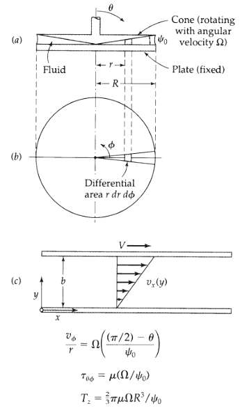
Parallel-disk viscometer (Fig. 3B.5), a fluid, whose viscosity is to be measured, is placed in the gap of thickness B between the two disks of radius R. One measures the torque Tz required to turn
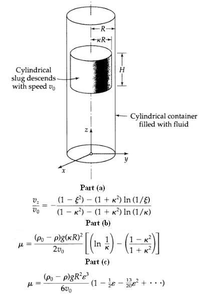
Circulating axial flow in an annulus (Fig. 3B.6), a rod of radius KR moves upward with a constant velocity v0 through a cylindrical container of inner radius R containing a Newtonian liquid, the
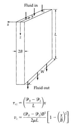
Momentum fluxes for creeping flow into a slot (Fig. 3.B-7). An incompressible Newtonian liquid is flowing very slowly into a thin slot of thickness 2B (in the y direction) and width W (in the z
Velocity distribution for creeping flow toward a slot (Fig. 3B.7) it is desired to get the velocity distribution given for the upstream region in the previous problem. We postulate that vθ = 0, vz =
Slow transverse flow around a cylinder (see Fig. 3.7-1). An incompressible Newtonian fluid approaches a stationary cylinder with a uniform, steady velocity v∞ in the positive x direction. When the
Radial flow between parallel disks (Fig. 3B.10). A part of a lubrication system consists of two circular disks between which a lubricant flows radially. The flow takes place because of a modified
Radial flow between two coaxial cylinders, consider an incompressible fluid, at constant temperature, flowing radially between two porous cylindrical shells with inner and outer radii kR and
Pressure distribution in incompressible fluids, Penelope is staring at a beaker filled with a liquid, which for all practical purposes can be considered as incompressible; let its density be P0. She
Flow of a fluid through a sudden contraction(a) An incompressible liquid flows through a sudden contraction from a pipe of diameter D1 into a pipe of smaller diameter D2. What does the Bernoulli
Torricelli's equation for efflux from a tank (Fig. 3B.14) a large uncovered tank is filled with a liquid to a height h. Near the bottom of the tank, there is a hole that allows the fluid to exit to
Shape of free surface in tangential annular flow (a) A liquid is in the annular space between two vertical cylinders of radii KR and R, and the liquid is open to the atmosphere at the top. Show
Flow in a slit with uniform cross flow (Fig. 3B.16). A fluid flows in the positive x-direction through a long flat duct of length L, width W, and thickness B, where L > > W >> B. The duct has porous
Parallel-disk compression viscometer 6 (Fig. 3C-1) A fluid fills completely the region between two circular disks of radius R. The bottom disk is fixed, and the upper disk is made to approach the
Normal stresses at solid surfaces for compressible fluids. Extend example 3.1-1 to compressible fluids. Show that τzz|z = 0 = (4/3μ + k)(∂ in p/∂t)z=0 Discuss the physical significance of this
Deformation of a fluid line (Fig. 3C.3). A fluid is contained in the annular space between two cylinders of radii KR and R. The inner cylinder is made to rotate with a constant angular velocity of
Alternative methods of solving the Couette vis-cometer problem by use of angular momentum concepts (Fig. 3.6-1). (a) By making a shell angular-momentum balance on a thin shell of thickness
Two-phase interfacial boundary conditions, in S2.1, boundary conditions for solving viscous flow problems were given. At that point no mention was made of the role of interfacial tension. At the
Derivation of the equations of change by integral theorems (Fig. 3D.1)(a) A fluid is flowing through some region of 3-dimensional space. Select an arbitrary "blob" of this fluid that is, a region
The equation of change for vorticity (a) By taking the curl of the Navier-Stokes equation of motion (in either the D/Dt form or the ?/?t form), obtain an equation for the vorticity, w = [? x v] of
Alternate form of the equation of motion show that, for an incompressible Newtonian fluid with constant viscosity, the equation of motion may be put into the form where
Time for attainment of steady flow in tube flow(a) A heavy oil with a kinematic viscosity of 3.45 x 10⁻⁴ m2/s, is at rest in a long vertical tube with a radius of 0.7 cm. The fluid is suddenly
Velocity near a moving sphere, a sphere of radius R is falling in creeping flow with a terminal velocity v∞ through a quiescent fluid of viscosity/μ. At what horizontal distance from the sphere
Construction of streamlines for the potential flow around a cylinder Plot the streamlines for the flow around a cylinder using the information in Example 4.3-1 by the following procedure: (a)
Comparison of exact and approximate profiles for flow along a flat plate compares the values of y√v∞x: obtained from Eq. 4.4-18 with those from Fig. 4.4-3, at the following values of
Numerical demonstration of the von Karman momentum balance(a) Evaluate the integrals in Eq. 4.4-13 numerically for the Blasius velocity profile given in Fig. 4.4-3. (b) Use the results of (a) to
Use of boundary-layer equations, air at 1 atm and 20oC flows tangentially on both sides of a thin, smooth flat plate of width W = 10 ft, and of length L = 3 ft in the direction of the flow. The
Entrance flow in conduits (a) Estimate the entrance length for laminar flow in a circular tube. Assume that the boundary-layer thickness S is given adequately by Eq. 4.4-17, with v∞ of the
Flow of a fluid with a suddenly applied constant wall stress, in the system studied in Example 4.1-1, let the fluid be at rest before t = 0. At time t = 0 a constant force is applied to the fluid at
Flow near a wall suddenly set in motion (approximate solution) (Fig. 4B.2). Applu procedure like that of Example 4.4-1 to get an approximate solution for Example 4.1.1(a) Integrate Eq. 4.4-1 over y
Creeping flow around a spherical bubble, when a liquid flows around a gas bubble, circulation takes place within the bubble. This circulation lowers the interfacial shear stress, and, to a first
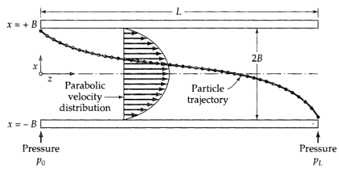
Use of the vorticity equation(a) Work Problem 2B.3 using the y-component of the vorticity equation (Eq. 3D.2-1) and the following boundary conditions: at x = ±B, vz = 0 and at x = 0, vz = vz, max.
Steady potential flow around a stationary sphere. 2 In Example 4.2-1 we worked through the creeping flow around a sphere. We now wish to consider the flow of an incompressible, inviscid fluid in
Potential flow near a stagnation point (Fig. 4B.6). (a) Show that the complex potential w = -v0z2 describes the flow near a plane stagnation point. (b) Find the velocity components vx(x, y)
Vortex flow(a) Show that the complex potential w = (iT/2π) in z describes the flow in a vortex. Verify that the tangential velocity is given by vθ = T/2ππ and that vr = 0. This type of flow is
The flow field about a line source considers the symmetric radial flow of an incompressible, inviscid fluid outward from an infinitely long uniform source, coincident with the z-axis of a cylindrical
Checking solutions to unsteady flow problems(a) Verify the solutions to the problems in Examples 4.1-1, 2, and 3 by showing that they satisfy the partial differential equations, initial conditions,
Radial flow through a porous medium (Fig. 4C.4), a fluid flows through a porous cylindrical shell with inner and outer radii R1 and R2, respectively. At these surfaces, the pressures are known to be
Flow near an oscillating wall? Show, by using Laplace tion to the problem stated in Eqs. 4.1-44 to 47 is transforms, that the complete solution to the problem stated in Eqs 4.1-44 to 47 is
Flows in the disk-and-tube system (Fig. 4D.3)9 (a) A fluid in a circular tube is caused to move tangentially by a tightly fitting rotating disk at the liquid surface at z = 0; the bottom of the
Unsteady annular flows? (a) Obtain a solution to the Navier-Stokes equation for the start-up of axial annular flow by a sudden impressed pressure gradient. Check your result against the
Stream functions for steady three-dimensional flow.(a) Show that the velocity functions pv = [∆ x A] and pv = [(∆ψ1) x (∆ψ2)] both satisfy the equation of continuity identically for steady
Pressure drop needed for laminar-turbulent transition. A fluid with viscosity 18.3 cp and density 1.32 g/cm3 is flowing in a long horizontal tube of radius 1.05 in. (2.67 cm). For what pressure
Velocity distribution in turbulent pipe flow water is flowing through a long, straight, level run of smooth 6.00 in. i.d. pipe, at a temperature of 68oF. The pressure gradient length of the pipe is
Average flow velocity in turbulent tube flow. (a) For the turbulent flow in smooth circular tubes, the function 1 is sometimes useful for curve-fitting purposes: near Re = 4 x 10³, n = 6; near
Mass flow rate in a turbulent circular jet.(a) Verify that the velocity distributions in Eqs. 5.6-21 and 22 do indeed satisfy the differential equations and boundary conditions.(b) Verify that Eq.
The eddy viscosity expression in the viscous sublayer, verify that Eq. 5.4-2 for the eddy viscosity comes directly from the Taylor series expression in Eq. 5.3-13.
Derivation of the equation of change for the Reynolds stresses. At the end of S5.2 it was pointed out that there is an equation of change for the Reynolds stresses. This can be derived by (a)
Kinetic energy of turbulence, by taking the trace of Eq. 5D.1-1 obtains the following: Interpret the equation
Pressure drop required for a pipe with fittings. What pressure drop is needed for pumping water at 20oC through a pipe of 25 cm diameter and 1234 m length at a rate of 1.97 m/s? The pipe is at the
Pressure difference required for flow in pipe with elevation change (Fig. 6A.2). Water at 68?F is to be pumped through 95 ft of standard 3-in. pipe (internal diameter 3.068 in.) into an overhead
Flow rate for a given pressure drop. How many gal/hr of water at 68o F can be delivered through a 1320-ft length of smooth 6.00-in. i. d. pipe under a pressure difference of 0.25 psi? Assume that the
Motion of a sphere in a liquid, a hollow sphere, 5.00 mm in diameter, with a mass of 0.0500 g, is released in a column of liquid and attains a terminal velocity of 0.500 cm/s. The liquid density is
Sphere diameter for a given terminal velocity. (a) Explain how to find the sphere diameter D corresponding to given values of v∞, p, ps, µ, and g by making a direct construction on Fig.
Estimation of void fraction of a packed column, a tube of 146 sq. in. cross section and 73 in. height is packed with spherical particles of diameter 2 mm. When a pressure difference of 158 psi is
Force on a water tower in a gale, a water tower has a spherical storage tank 40 ft in diameter. In a 100-mph gale what is the force of the wind on the spherical tank at 0°C? Take the density of air
Flow of gas through a packed column, a horizontal tube with diameter 4 in. and length 5.5 ft is packed with glass spheres of diameter 1/16 in., and the void fraction is 0.41. Carbon dioxide is to be
Effect of error in friction factor calculations, in a calculation using the Blasius formula for turbulent flow in pipes, the Reynolds number used was too low by 4%. Calculate the resulting error in
Friction factor for flow along a flat plate2 (a) An expression for the drag force on a flat plate, wetted on both sides, is given in Eq. 4.4-30. This equation was derived by using laminar
Friction factor for laminar flow in a slit, use the results of Problem 2B.3 to show that for the laminar flow in a thin slit of thickness 2B the friction factor is f = 12/Re, if the Reynolds number
Friction factor for a rotating disk, a thin circular disk of radius R is immersed in a large body of fluid with density p and viscosity µ. If a torque Tz is required to make the disk rotate at an
Turbulent flow in horizontal pipes, a fluid is flowing with a mass flow rate w in a smooth horizontal pipe of length L and diameter D as the result of a pressure difference P0 - PL. The flow is known
Inadequacy of mean hydraulic radius for laminar flow(a) For laminar flow in an annulus with radii kR and Rr use Eqs. 6.2-17 and 18 to get an expression for the average velocity in terms of the
Falling sphere in Newton's drag-law region, a sphere initially at rest at z = 0 falls under the influence of gravity. Conditions are such that, after a negligible interval, the sphere falls with a
Design of an experiment to verify the f vs. Re chart for spheres, it is desired to design an experiment to test the friction factor chart in Fig. 6.3-1 for flow around a sphere. Specifically, we want
Friction factor for flow past an infinite cylinder, the flow past a long cylinder is very different from the flow past a sphere, and the method introduced in S4.2 can-not be used to describe this
Two-dimensional particle trajectories, a sphere of radius R is fired horizontally (in the x direction) at high velocity in still air above level ground. As it leaves the propelling device, an
Friction factor for a bubble in a clean liquid, when a gas bubble moves through a liquid, the bulk of the liquid behaves as if it were in potential flow; that is, the flow field in the liquid phase
Pressure rise in a sudden enlargement (Fig. 7.6-1). An aqueous salt solution is flowing through a sudden enlargement at a rate of 450 U. So gal/min = 0.0384 m3/s. The inside diameter of the smaller
Pumping a hydrochloric acid solution (Fig. 7A.2), a dilute HC1 solution of constant density and viscosity (p = 62.4lbm/ft3, µ = 1 cp) is to be pumped from tank I to tank 2 with no overall change in
Compressible gas flow in a cylindrical pipe, gaseous nitrogen is in isothermal turbulent flow at 25°C through a straight length of horizontal pipe with 3-in. inside diameter at a rate of 0.28lbm/s.
Incompressible flow in an annulus, Water at 60°F is being delivered from a pump through a coaxial annular conduit 20.3 ft long at a rate of 241 U.S. gal/min, the inner and outer radii of the annular
Force on a U-bend (Fig. 7A.5). Water at 68°F (p = 62.4lbm/ft3, µ = 1 cp) is flowing in turbulent flow in a U-shaped pipe bend at 3 ft3/s. What is the horizontal force exerted by the water on the
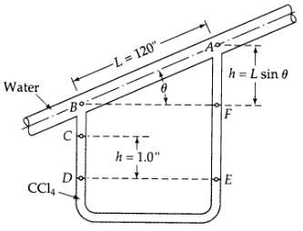
Flowerate calculation (Fig. 7A.6) for the system shown in the figure, calculate the volume flow rate of water at 68°F.
Evaluation of various velocity averages from Pitot tube data. Following are some experimental data1 for a Pitot tube traverse for the flow of water in a pipe of internal radius 3.06 in.: Plot these
Velocity averages from the 1/7 power law. Evaluate the velocity ratios in Problem cording to the velocity distribution in Eq. 5.1-4.
Relation between force and viscous loss for flow in conduits of variable cross section equation 7.5-6 gives the relation Ff→s = pSEv between the drag force and viscous loss for straight conduits of
Flow through a sudden enlargement (Fig. 7.6-1). A fluid is flowing through a sudden enlargement, in which the initial and final diameters are D1 and D2 respectively. At what ratio D2/D1 will the
Flow between two tanks (Fig. 7B.4). Case I: A fluid flows between two tanks A and B because PA > PB. The tanks are at the same elevation and there is no pump in the line. The connecting line has a
Revised design of an air duct (Fig. 7B.5), a straight, horizontal air duct was to be installed in a factory. The duct was supposed to be 4 ft x 4 ft in cross section. Because of an obstruction, the
Multiple discharges into a common conduit (Fig. 7B.6) extend Example 7.6-1 to an incompressible fluid discharging from several tubes into a larger tube with a net increase in cross section. Such
Inventory variations in a gas reservoir, a natural gas reservoir is to be supplied from a pipeline at a steady rate of go w1 lbm/hr. During a 24-hour period, the fuel demand from the reservoir, w2,
Change in liquid height with time (Fig. 7.1-1). (a) Derive Eq. 7.1-4 by using integral calculus. (b) In Example 7.1-1, obtain the expression for the liquid height h as a function of time
Draining of a cylindrical tank with exit pipe (Fig. 7B.9)(a) Rework Example 7.1-1, but with a cylindrical tank instead of a spherical tank. Use the quasi-steady-state approach; that is, use the
Efflux time for draining a conical tank (Fig. 7B.10), a conical tank, with dimensions given in the figure, is initially filled with a liquid. The liquid is allowed to drain out by gravity. Determine
Disintegration of wood chips (Figure 7B.11). In the manufacture of paper pulp the cellulose fibers of wood chips are freed from the lignin binder by heating in alkaline solutions under pressure in
Criterion for Vapor-Free Flow in a Pipeline, to ensure that a pipeline is completely liquid-filled, it is necessary that p > Pvap at every point. Apply this criterion to the system in Fig. 7.5-1,
End corrections in tube viscometers (Fig. 7C.1)? In analyzing tube-flow viscometric data to determine viscosity, one compares pressure drop versus flow rate data with the theoretical expression (the
Derivation of the macroscopic balances from the equations of change, derive the macroscopic mass and momentum balances by integrating the equations of continuity and motion over the flow system of
Flow of a polyisoprene solution in a pipe, a 13.5% (by weight) solution of polyisoprene in isopentane has the following power law parameters at 323 K: n = 0.2 and m = 5 x 10³ Pa ∙ sn. It is being
Pumping of a polyethylene oxide solution a 1% aqueous solution of polyethylene oxide at 333 K has power law parameters n = 0.6 and m = 0.50 Pa ∙ sn. The solution is being pumped between two tanks,
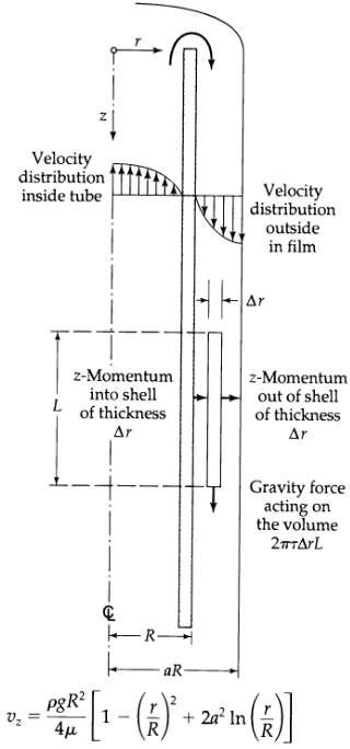
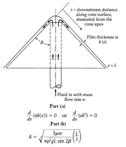
Flow of a polymeric film work the problem in S2.2 for the power law fluid. Show that the result simplifies properly to the Newtonian result.
Power law flow in a narrow slit, in Example 8.3-2 show how to derive the velocity distribution for the region – < x < 0, is it possible to combine this result with that in Eq. 8.3-13 into one
Non-Newtonian flow in an annulus, rework Problem 2B.7 for the annular flow of a power law fluid with the flow being driven by the axial motion of the inner cylinder. (a) Show that the velocity
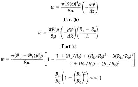
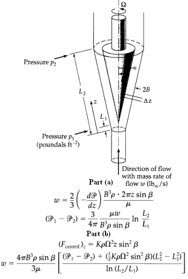
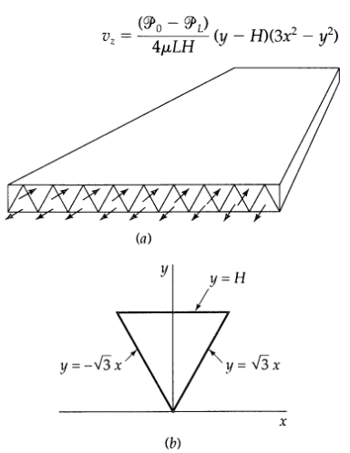
Flow of a polymeric liquid in a tapered tribe work Probtem 2B.10 for a power law fluid, using the lubrication approximation.
Derivation of the Buckingham-Reiner equation2?rework Example 8.3-1 for the Bingham model, first find the velocity distribution. Then show that the mass rate of flow is given by in which ?R = (P0 ?
The complex-viscosity components for the Jeffreys fitrid,(a) Work Example 8.4-1 for the Jeffreys model of Eq. 8.4-4, and show that the results are Eqs. 8.5-12 and 13. How are these results related to
Stress relaxation after cessation of shear flow. A viscoelastic fluid is in steady-state flow between a pair of parallel plates, with vx = ?y If the flow is suddenly stopped (i.e., ?/becomes zero),
Draining of a tank with an exit pipe (Fig. 7B.9) rework Problem 7B.9 (a) for the power law fluid
The Giesekus model(a) Use the results in Table 8.5-1 to get the limiting values for the non-Newtonian viscosity and the normal stress differences as the shear rate goes to zero.(b) Find the limiting
Squeezing flow between parallel disks (Fig. 3C.1).4 Rework Problem 3C.l (g) for the power law fluid. This device can be useful for determining the power law parameters for materials that are highly
Showing 100 - 200
of 6780
1
2
3
4
5
6
7
8
9
10
11
12
13
14
15
Last